Nissan Murano Z51. Manual - part 200


  Главная      Nissan     Nissan Murano Z51 (2010 year) - Service Manual


поиск по сайту            


содержание   ..  198  199  200  201   ..


Nissan Murano Z51. Manual - part 200


AV

REAR VIEW MONITOR SYSTEM

AV-579

< SYSTEM DESCRIPTION >

[BOSE AUDIO WITH NAVIGATION]

C

D

E

F

G

H

I

J

K

L

M

B

A

O

P

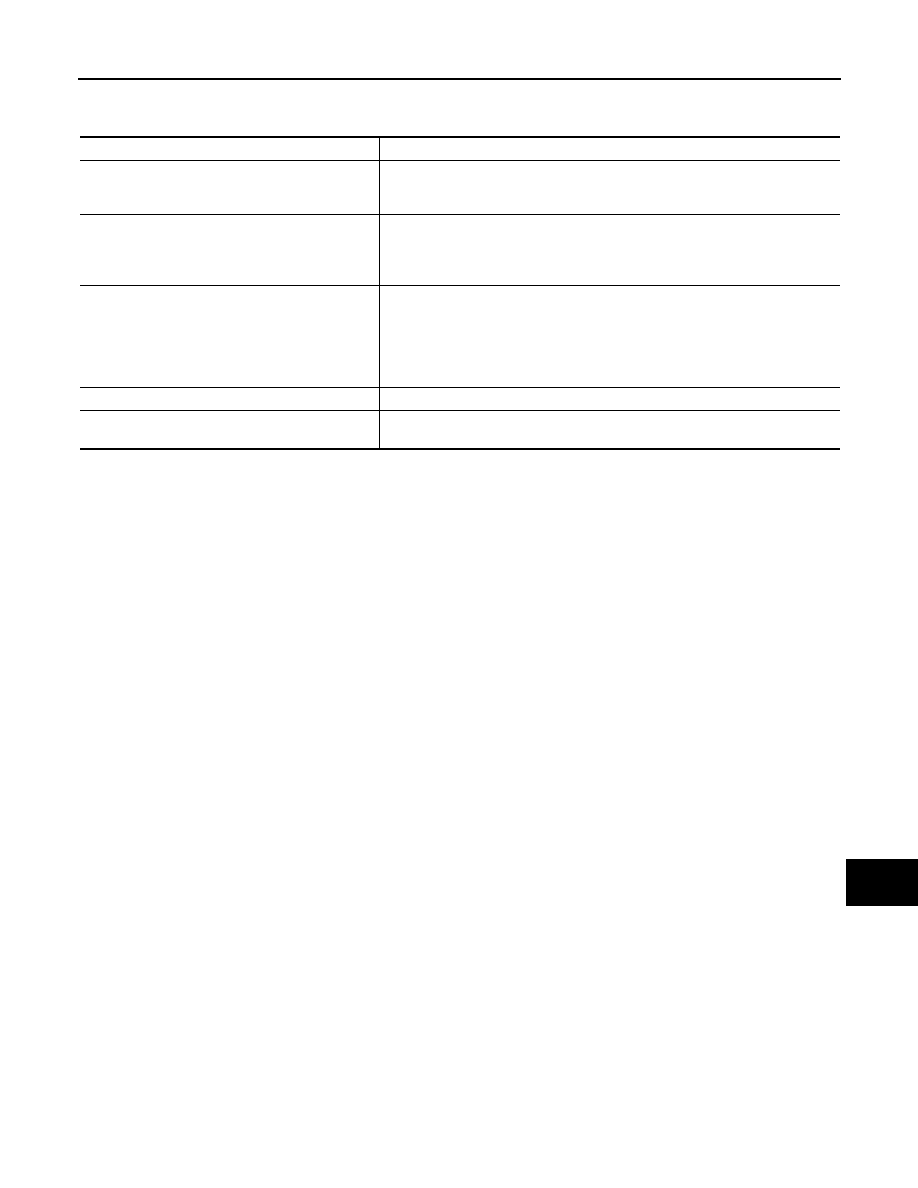
Component Description

INFOID:0000000005528686

Part name

Description

AV CONTROL UNIT

• Image on display is changed to rear view monitor image with serial communi-

cation between AV control unit and front display unit.

• Warning displayed in rear view monitor image is illustrated.

FRONT DISPLAY UNIT

• Camera image signal is transmitted from camera control unit, and RGB signal 

for warning display is transmitted from AV control unit.

• Rear view monitor image is changed with the communication for AV control 

unit.

CAMERA CONTROL UNIT

• Camera image signal is input from rear view camera, and camera image is in-

dicated on the front display unit.

• Power (camera ON signal) is transmitted to rear view camera.
• Controlled by AV communication transmitted from AV control unit.
• AV control unit recognizes the presence of camera system with camera con-

nection recognition signal.

REAR VIEW CAMERA

The image of vehicle rear view is transmitted to camera control unit.

STEERING ANGLE SENSOR

Steering signal necessary for possible route line control is transmitted to camera 
control unit.

AV-580

< SYSTEM DESCRIPTION >

[BOSE AUDIO WITH NAVIGATION]

AUDIO SYSTEM

AUDIO SYSTEM

System Diagram

INFOID:0000000005528687

NOTE:
• Woofer, illustrated in the above figure, integrates two woofers and a woofer amp.
• The name MULTIFUNCTION SWITCH indicates the integration of PRESET SWITCH and MULTIFUNCTION

SWITCH virtually.

• An antenna base integrated with radio antenna amp. and satellite

radio antenna is adopted.

System Description

INFOID:0000000005528688

The audio system is equipped with the following functions. Each function is operated with multifunction switch,
preset switch, touch panel, steering switch or audio recognition. Operation status of AUDIO is indicated in the
display.

FUNCTION DESCRIPTION

Operating Signal

Audio system operation can be performed with multifunction switch, preset switch, steering switch, touch
panel function or voice recognition function.

JSNIA1094GB

JSNIA1062GB

Function

AM/FM radio

Satellite radio

CD

Music Box (Hard Disk Drive)

CF (Compact Flash)

iPod connection

AUX mode

AV

AUDIO SYSTEM

AV-581

< SYSTEM DESCRIPTION >

[BOSE AUDIO WITH NAVIGATION]

C

D

E

F

G

H

I

J

K

L

M

B

A

O

P

• Operating signal is transmitted to AV control unit with AV communication when it is operated by multifunction

switch or preset switch. The disk ejection operating signal is performed by wiring harness.

• Operating signal is transmitted to AV control unit with steering switch signal when it is operated by steering

switch.

• Refer to 

AV-567, "System Description"

 for explanation of voice recognition function and touch panel function.

Screen Front Display

• Switching of display is performed with serial communication between front display unit and AV control unit.
• The image signal to front display operating condition is performed with RGB image signal, RGB area signal

and RGB synchronizing signal.

AM/FM Radio Mode

• AM/FM radio tuner is built into AV control unit.
• AM/FM radio wave is received by rod antenna, next it is amplified by antenna amp., and finally it is input to

AV control unit. The FM sub antenna is installed on the back door window glass and the AV control unit is
received.

• Audio signal is input to BOSE amp. and BOSE amp. outputs to woofer and each speaker for AV control unit.

Satellite Radio Mode

• Satellite radio tuner is built into AV control unit.
• Audio wave (satellite radio) is received by antenna base (satellite antenna), and it is input to AV control unit.

AV control unit outputs audio signal to BOSE amp. The signal is also outputted from BOSE amp. to both
woofer and each speaker.

CD Mode

• CD function is built into AV control unit.
• AV control unit outputs audio signal to BOSE amp. and BOSE amp. outputs to woofer and each speaker

when CD is inserted to AV control unit.

Music Box Mode

• Music CD data is stored on HDD that is built into AV control unit, and it can be played.
• AV control unit outputs music (audio signal) that is stored on HDD to BOSE amp., and BOSE amp. outputs to

woofer and each speaker.

CF Mode

• AV control unit has built in CF replay function.
• Music (audio signal) that is stored in CF outputs to BOSE amp., and BOSE amp. outputs to woofer and each

speaker when CF is inserted into AV control unit.

iPod Connection

• Connect iPod

®

 and iPod adapter with wire harness and iPod adapter input iPod sound signal from iPod

®

.

When iPod mode is selected, iPod adapter outputs iPod sound signal to AV control unit. AV control unit out-
put sound signal to BOSE amp., and BOSE amp. output sound signal to woofer and each speaker. 

• Receiving/transmitting of iPod

®

 operation signals are performed as follows:

- between AV control unit and iPod adapter: AV communication.
- between iPod

®

 and iPod adapter: serial communication.

• The iPod

®

 connection status can be recognized if iPod adapter receives iPod connection recognition signal.

• The iPod adapter can charge iPod

®

.

AUX Mode

Refer to 

AV-567, "System Description"

.

AV-582

< SYSTEM DESCRIPTION >

[BOSE AUDIO WITH NAVIGATION]

AUDIO SYSTEM

Component Parts Location

INFOID:0000000005528689

1.

Center speaker

2.

Front squawker LH

3.

Front door speaker LH

4.

Rear door speaker LH

5.

Rear speaker LH

6.

BOSE amp.

7.

Woofer

8.

Rear view camera

9.

Camera control unit

10. Rear speaker RH

11.

Antenna base (antenna amp. and 
satellite antenna) 

12. Rear door speaker RH

13. Front door speaker RH

14. Front squawker RH

15. Microphone

16. GPS antenna

17. Steering angle sensor

18. Steering switch

19. Auxiliary input jacks

20. iPod connector

21. iPod adapter

22. Preset switch

23. AV control unit

24. Multifunction switch

25. Front display unit

A.

Luggage floor finisher is removed 
condition

B.

Luggage side finisher lower RH is re-
moved condition

C.

Combination meter is removed condi-
tion

D.

Spiral cable part

E.

Console finisher is removed condition

JSNIA1096ZZ


содержание   ..  198  199  200  201   ..