содержание .. 1396 1397 1398 1399 ..
Nissan Murano Z51. Manual - part 1398
ST-30
< REMOVAL AND INSTALLATION >
STEERING GEAR AND LINKAGE
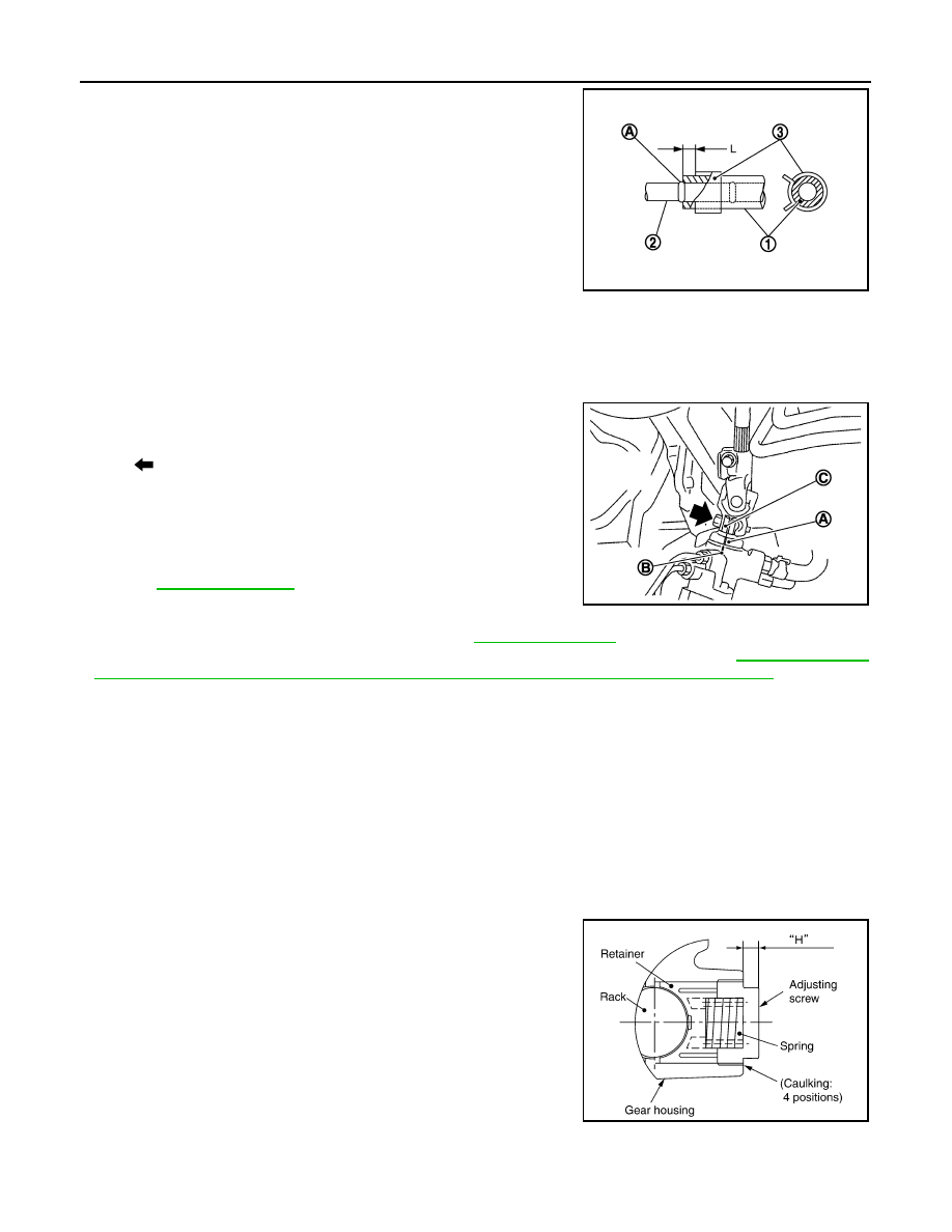
• When installing low pressure hose (1), refer to the figure.
CAUTION:
• Never apply fluid to the hose (1) and tube (2).
• Insert hose securely until it contacts spool (A) of tube.
• Leave clearance (L) when installing clamp (3).
• When installing lower joint to steering gear assembly, follow the procedure listed below.
- Set rack of steering gear in the neutral position.
NOTE:
To get the neutral position of rack, turn gear-sub assembly and measure the distance of inner socket, and
then measure the intermediate position of the distance.
- Align rear cover cap projection (A) with the marking position of
gear housing assembly (B).
- Install slit part of lower joint (C) aligning with the rear cover cap
projection (A). Make sure that the slit part of lower joint (C) is
aligned with rear cover cap projection (A) and the marking position
of gear housing assembly (B).
• After installation, bleed air from the steering hydraulic system.
.
• Perform final tightening of nuts and bolts on each part under
unladen conditions with tires on level ground when removing steer-
ing gear assembly. Check wheel alignment. Refer to
.
• Adjust neutral position of steering angle sensor after checking wheel alignment. Refer to
MENT OF STEERING ANGLE SENSOR NEUTRAL POSITION : Special Repair Requirement"
Disassembly and Assembly
INFOID:0000000005514485
DISASSEMBLY
1.
Remove low pressure piping.
CAUTION:
• Disassemble and assemble steering gear assembly by fixing the mounting area with a vise using
copper plates.
• Clean steering gear assembly with kerosene before disassembling. Be careful to avoid splash-
ing or applying any kerosene over connector of discharge port or return port.
2.
Remove cylinder tubes from gear housing assembly.
3.
Remove rear cover cap from gear-sub assembly.
4.
Measure adjusting screw height “H”, and loosen adjusting
screw.
CAUTION:
• Never loosen adjusting screw 2 turns or more.
• Replace steering gear assembly if adjusting screw is
loosened 2 turns or more and it is removed.
5.
Remove gear-sub assembly from gear housing assembly.
6.
Remove O-ring from gear housing assembly.
7.
Loosen outer socket lock nut, and remove outer socket.
8.
Remove boot clamps, and then remove boot from inner socket.
CAUTION:
Never damage inner socket and gear housing assembly when removing boot. Inner socket and
gear housing assembly must be replaced if inner socket and gear housing assembly are damaged
because it may cause foreign material interfusion.
Standard
L
: 3 – 8 mm (0.12 – 0.31 in)
JSGIA0118ZZ
: Bolt
JSGIA0111ZZ
SGIA0624E