содержание .. 1044 1045 1046 1047 ..
Nissan Murano Z51. Manual - part 1046
MWI-42
< DTC/CIRCUIT DIAGNOSIS >
B2268 WATER TEMP
B2268 WATER TEMP
Description
INFOID:0000000005524869
The engine coolant temperature signal is transmitted from ECM to the combination meter via CAN communi-
cation.
DTC Logic
INFOID:0000000005524870
DTC DETECTION LOGIC
Diagnosis Procedure
INFOID:0000000005524871
1.
PERFORM SELF-DIAGNOSIS OF ECM
Perform “Self Diagnosis Result” of ECM, and repair or replace malfunctioning parts.
>> Refer to
EC-116, "CONSULT-III Function"
.
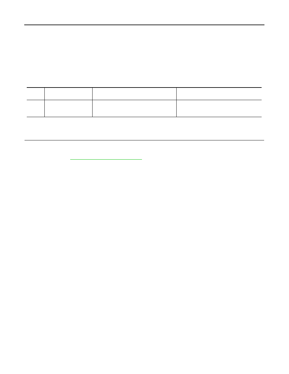
DTC
Display contents of
CONSULT-III
Diagnostic item is detected when ...
Probable malfunction location
B2268
WATER TEMP
ECM continuously transmits abnormal engine
coolant temperature signals for 60 seconds or
more
• Engine coolant temperature sensor
• ECM