Nissan Murano Z51. Manual - part 12


  Главная      Nissan     Nissan Murano Z51 (2010 year) - Service Manual


поиск по сайту            


содержание   ..  10  11  12  13   ..


Nissan Murano Z51. Manual - part 12


ADP-40

< SYSTEM DESCRIPTION >

DIAGNOSIS SYSTEM (DRIVER SEAT CONTROL UNIT)
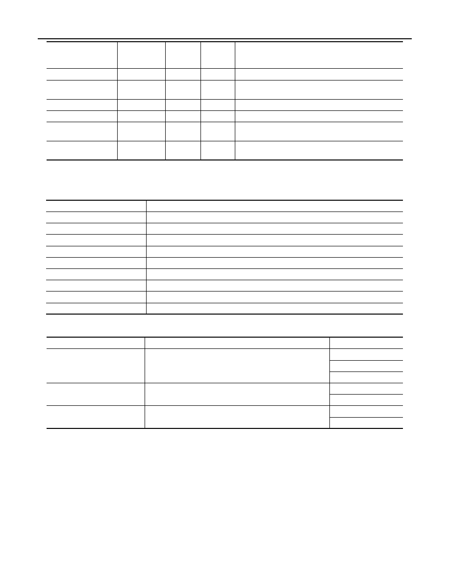
ACTIVE TEST

CAUTION:

When driving vehicle, do not perform active test.

WORK SUPPORT

KEYLESS ID

×

×

Key ID status judged from the key ID signal.

KYLS DR UNLK

“ON/OFF”

×

×

ON/OFF status judged from the driver side door unlock ac-
tuator output switch signal.

VHCL SPEED (ABS)

“ON/OFF”

×

×

ON/OFF status judged from vehicle speed signal.

HANDLE

“RHD/LHD”

×

×

RHD/LHD status judged from handle position signal.

TRANSMISSION

“AT or CVT/

MT”

×

×

AT or CVT/MT status judged from transmission.

STEERING STATUS

“LOCK/UN-

LOCK”

×

×

LOCK/UNLOCK status judged from steering lock unit.

Monitor Item

Unit

Main

Signals

Selection 

From 

Menu

Contents

Test item

Description

SEAT SLIDE

Activates/deactivates the sliding motor.

SEAT RECLINING

Activates/deactivates the reclining motor.

SEAT LIFTER FR

Activates/deactivates the lifting motor (front).

SEAT LIFTER RR

Activates/deactivates the lifting motor (rear).

TILT MOTOR

Activates/deactivates the tilt motor.

TELESCO MOTOR

Activates/deactivates the telescopic motor.

MIRROR MOTOR RH

Activates/deactivates the mirror motor (passenger side).

MIRROR MOTOR LH

Activates/deactivates the mirror motor (driver side).

MEMORY SW INDCTR

Turns ON/OFF the memory indicator.

Work item

Content

Item

SEAT SLIDE VOLUME SET

The amount of seat sliding for entry/exit assist can be selected 
from 3 items.

40 mm

80 mm

150 mm

EXIT TILT SETTING

Entry/exit assist (steering column) can be selected: 
ON (operated) – OFF (not operated)

ON

OFF

EXIT SEAT SLIDE SETTING

Entry/exit assist (seat) can be selected: 
ON (operated) – OFF (not operated)

ON

OFF

U1000 CAN COMM CIRCUIT

ADP-41

< DTC/CIRCUIT DIAGNOSIS >

C

D

E

F

G

H

I

K

L

M

A

B

ADP

N

O

P

DTC/CIRCUIT DIAGNOSIS

U1000 CAN COMM CIRCUIT

Description

INFOID:0000000005515299

CAN (Controller Area Network) is a serial communication line for real time applications. It is an on-vehicle mul-
tiplex communication line with high data communication speed and excellent error detection ability. Modern
vehicle is equipped with many electronic control unit, and each control unit shares information and links with
other control units during operation (not independent). In CAN communication, control units are connected
with 2 communication lines (CAN H-line, CAN L-line) allowing a high rate of information transmission with less
wiring. Each control unit transmits/receives data but selectively reads required data only.

DTC Logic

INFOID:0000000005515300

DTC DETECTION LOGIC

DTC CONFIRMATION PROCEDURE

1.

STEP 1

Turn ignition switch ON and wait at least 3 seconds.

>> GO TO 2.

2.

STEP 2

Check “Self diagnostic result” with CONSULT-III.

Is the DTC detected?

YES

>> Perform diagnosis procedure. Refer to 

ADP-41, "Diagnosis Procedure"

.

NO

>> INSPECTION END

Diagnosis Procedure

INFOID:0000000005515301

Refer to 

LAN-17, "Trouble Diagnosis Flow Chart"

.

Special Repair Requirement

INFOID:0000000005515302

Refer to 

ADP-9, "SYSTEM INITIALIZATION : Description"

.

DTC No.

Trouble diagnosis 

name

DTC detecting condition

Possible cause

U1000

CAN COMM CIR-
CUIT

• Driver seat control unit cannot communicate to other 

control units.

• Driver seat control unit cannot communicate for more 

than the specified time.

• Harness or connectors

(CAN communication line is 
open or shorted)

ADP-42

< DTC/CIRCUIT DIAGNOSIS >

U1010 CONTROL UNIT (CAN)

U1010 CONTROL UNIT (CAN)

Description

INFOID:0000000005515303

CAN (Controller Area Network) is a serial communication line for real time applications. It is an on-vehicle mul-
tiplex communication line with high data communication speed and excellent error detection ability. Modern
vehicle is equipped with many electronic control unit, and each control unit shares information and links with
other control units during operation (not independent). In CAN communication, control units are connected
with 2 communication lines (CAN-H line, CAN-L line) allowing a high rate of information transmission with less
wiring. Each control unit transmits/receives data but selectively reads required data only.
CAN Communication Signal Chart, refer to 

LAN-27, "CAN Communication Signal Chart"

.

DTC Logic

INFOID:0000000005515304

DTC DETECTION LOGIC

Diagnosis Procedure

INFOID:0000000005515305

1.

REPLACE DRIVER SEAT CONTROL UNIT

When DTC [U1010] is detected, replace driver seat control unit.

>> Replace driver seat control unit.Refer to 

ADP-209, "Removal and Installation"

.

DTC 

No.

Trouble diagnosis name

DTC detecting condition

Possible cause

U1010

CONTROL UNIT (CAN)

When detecting error during the initial diagnosis of CAN con-
troller of driver seat control unit.

• Driver seat control unit

B2130 EEPROM

ADP-43

< DTC/CIRCUIT DIAGNOSIS >

C

D

E

F

G

H

I

K

L

M

A

B

ADP

N

O

P

B2130 EEPROM

DTC Logic

INFOID:0000000005515306

DTC DETECTION LOGIC

DTC CONFIRMATION PROCEDURE

1.

STEP 1

Turn ignition switch ON.

>> GO TO 2.

2.

STEP 2

Check “Self diagnostic result” with CONSULT-III.

Is the DTC detected? 

YES

>> Perform diagnosis procedure. Refer to 

ADP-43, "Diagnosis Procedure"

.

NO

>> INSPECTION END

Diagnosis Procedure

INFOID:0000000005515307

1.

PERFORM DTC CONFIRMATION PROCEDURE

1.

Turn ignition switch ON.

2.

Check “Self diagnostic result” with CONSULT-III.

3.

Erase the DTC.

4.

Perform DTC confirmation procedure. Refer to 

ADP-43, "DTC Logic"

.

Is the DTC displayed again?

YES

>> GO TO 2.

NO

>> Check intermittent incident. Refer to 

GI-39, "Intermittent Incident"

.

2.

REPLACE DRIVER SEAT CONTROL UNIT

Replace driver seat control unit. Refer to 

ADP-209, "Removal and Installation"

.

>> INSPECTION END

DTC No.

Trouble diagnosis 

name

DTC detecting condition

Possible cause

B2130

EEPROM

Driver seat control unit detected CPU malfunction.

• Driver seat control unit


содержание   ..  10  11  12  13   ..