содержание .. 755 756 757 758 ..
Nissan Murano. Manual - part 757
FRONT DRIVE SHAFT
FAX-23
< REMOVAL AND INSTALLATION >
[2WD]
C
E
F
G
H
I
J
K
L
M
A
B
FAX
N
O
P
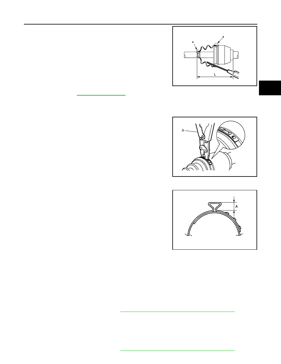
9.
Install the boot securely into grooves (indicated by “*” marks)
shown in the figure.
CAUTION:
If grease adheres to the boot mounting surface (indicated
by “*” mark) on the housing assembly or joint sub-assem-
bly, boot may be removed. Remove all grease from the boot
mounting surface.
10. To prevent the deformation of the boot, adjust the boot installa-
tion length (L) to the specified value shown below by inserting
the suitable tool into inside of the boot from the large diameter
side of the boot and discharging the inside air.
CAUTION:
• If the boot mounting length exceeds the standard, it may cause breakage of boot.
• Be careful not to touch the inside of the boot with a tip of tool.
11. Secure the large and small ends of the boot with boot bands
using the boot band crimping tool (A) [SST: KV40107300 (
—
)].
CAUTION:
Never reuse boot band.
NOTE:
Secure boot band so that dimension (A) meets the specification
as shown in the figure.
12. Secure joint sub-assembly and housing assembly, and then
make sure that they are in the correct position when rotating
boot. Reinstall them using boot bands when boot installation
positions become incorrect.
CAUTION:
Never reuse boot band.
TRANSAXLE SIDE
TRANSAXLE SIDE : Disassembly and Assembly
INFOID:0000000009717905
DISASSEMBLY
Left Side
1.
Fix drive shaft with a vise.
CAUTION:
Protect shaft using aluminum or copper plates when fixing with a vise.
2.
Disassemble boot (wheel side). Refer to
FAX-22, "WHEEL SIDE : Disassembly and Assembly"
3.
Remove boot bands and boot (transaxle side).
Right Side
1.
Fix drive shaft with a vise.
CAUTION:
Protect shaft using aluminum or copper plates when fixing with a vise.
2.
Disassemble boot (wheel side). Refer to
FAX-22, "WHEEL SIDE : Disassembly and Assembly"
L
: Refer to
.
JPDIF0222ZZ
JPDIF0012ZZ
A
: 7.0 mm (0.276 in) or less
JPDIF0268ZZ