содержание .. 282 283 284 285 ..
Nissan Murano. Manual - part 284
DAS-26
< ECU DIAGNOSIS INFORMATION >
[LDW]
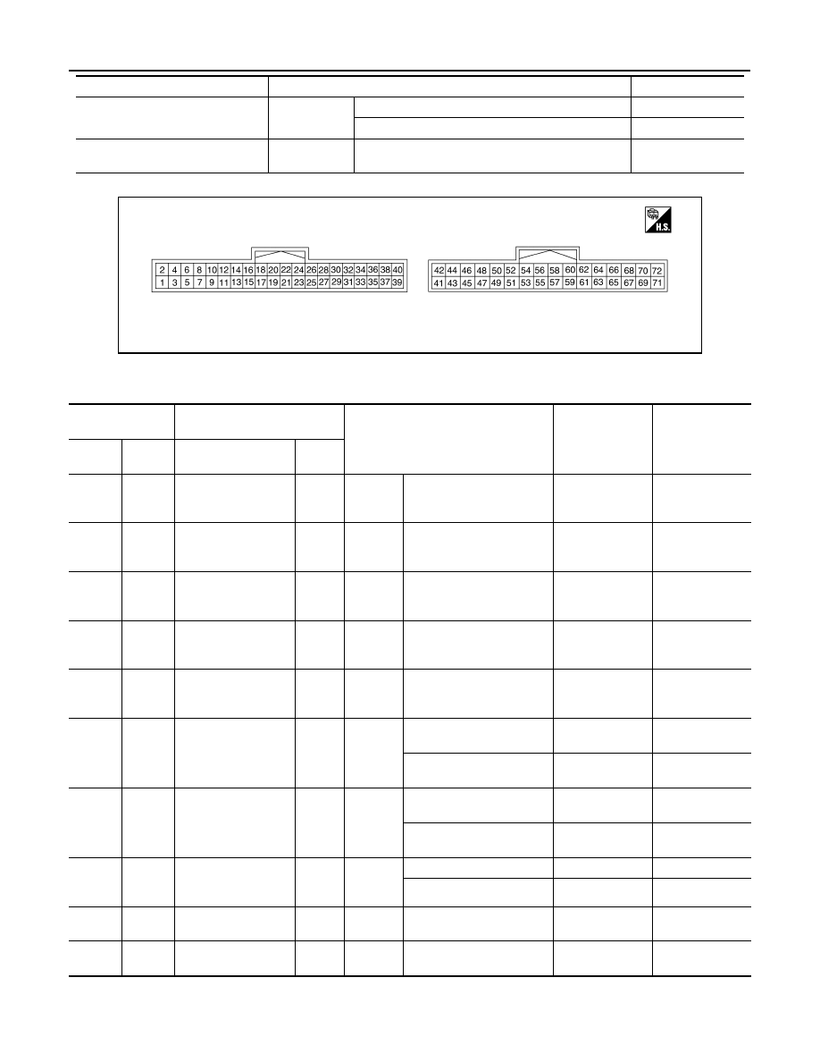
CAMERA CONTROL UNIT
TERMINAL LAYOUT
PHYSICAL VALUES
PUMP COMM STATUS
[OK/NG]
Ignition switch
ON
When communication signal is input
OK
Other than the above
NG
ITS SW 2 IND
[No setting]
Ignition switch
ON
—
No setting
Monitor Item
Condition
Value/Status
JSNIA4749ZZ
Terminal
(Wire color)
Description
Condition
Standard value
Reference value
(Approx.)
+
–
Signal name
Input/
Output
1
(B)
Ground
Ground
—
Ignition
switch
ON
—
0 - 0.1 V
0 V
2
(V)
1
(B)
Battery power supply
Input
Ignition
switch
OFF
—
9.5 - 16 V
Battery voltage
3
(G)
1
(B)
Ignition signal
Input
Ignition
switch
ON
—
9.5 - 16 V
Battery voltage
7
(R)
Ground
BSW indicator LH
Output
Ignition
switch
ON
Approx. 2 sec. after ignition
switch OFF
⇒
ON (bulb
check).
5.5 - 16 V
6.0 V
8
(G)
Ground
BSW indicator RH
Output
Ignition
switch
ON
Approx. 2 sec. after ignition
switch OFF
⇒
ON (bulb
check)
5.5 - 16 V
6.0 V
15
(BR)
Ground
Warning systems ON
indicator
Output
Ignition
switch
ON
Warning systems ON indi-
cator ON
0 - 0.1 V
0 V
Warning systems ON indi-
cator OFF
9.5 - 16 V
12.0 V
17
(GR)
Ground
Warning systems
switch
Input
Ignition
switch
ON
When warning systems
switch is not pressed
9.5 - 16 V
12.0 V
When warning systems
switch is pressed
0 - 0.1 V
0 V
25
(R)
1
(B)
Reverse signal
Input
Ignition
switch
ON
R position
9.5 - 16 V
12.0 V
Other than R position
0 - 0.1 V
0 V
27
(L)
—
CAN-H
Input/
Output
—
—
—
—
28
(P)
—
CAN-L
Input/
Output
—
—
—
—