Nissan X-Trail 32. Manual - part 493


  Главная      Nissan     Nissan X-Trail 32 - Service Manual


поиск по сайту            


содержание   ..  491  492  493  494   ..


Nissan X-Trail 32. Manual - part 493


BACK DOOR LOCK

DLK-313

< REMOVAL AND INSTALLATION >

[TYPE 1]

C

D

E

F

G

H

I

J

L

M

A

B

DLK

N

O

P

2.

Check the lock/unlock operation of door lock.

3.

Check door lock assembly for poor lubrication. Apply body
grease to door lock if necessary.

DOOR LOCK : Unlock procedures

INFOID:0000000010708307
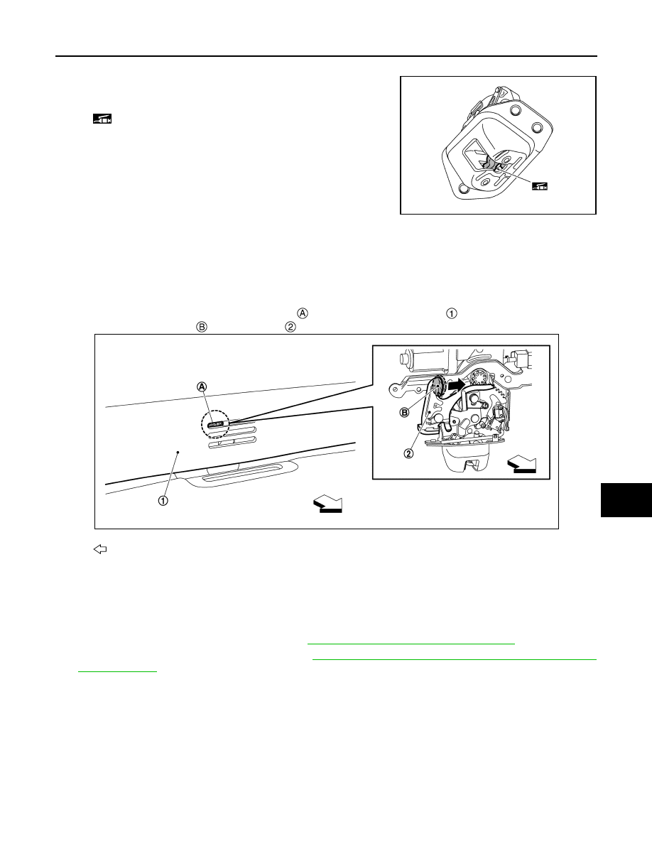
UNLOCK PROCEDURES

NOTE:
Release lock according to the following procedures when lock cannot be unlocked due to a malfunction of
door lock assembly or battery discharge.
Insert a screwdriver, etc. into tool insertion hole 

 of back door inner finisher 

, and then back door lock is

unlocked by operating knob 

 of cancel lever 

 in the direction of arrow as shown in the figure.

SPINDLE UNIT

SPINDLE UNIT : Removal and Installation

INFOID:0000000010708308

REMOVAL

1.

Disconnect battery negative terminal. Refer to 

PG-139, "R9M : Removal and Installation"

.

2.

Remove luggage side upper finisher. Refer to 

INT-45, "LUGGAGE SIDE UPPER FINISHER : Removal

and Installation"

.

: Body grease

JMKIB1220ZZ

: Vehicle front

JMKIB3161ZZ

DLK-314

< REMOVAL AND INSTALLATION >

[TYPE 1]

BACK DOOR LOCK

3.

Disconnect spindle unit harness connector.

4.

Remove harness grommet 

 from back main center pillar 

,

and then pull out spindle unit harness from vehicle body.

5.

Support back door with the proper material to prevent it from falling.

WARNING:

Bodily injury may occur if no supporting rod is holding the back door open when removing the
back door stay.

6.

Apply protective tape (A) to back door touch sensor around spin-
dle unit for preventing damage.

7.

Remove metal clip 

 located on connection between back door

stay 

 and stud ball 

 using a remover tool (A) according to the

numerical order 1

2 indicated by arrows as shown in the figure.

8.

Disengage spindle unit and stud ball of back door side.

9.

Remove back door stay upper bracket mounting bolts, and then remove spindle unit with back door stay
upper bracket.

INSTALLATION

Note the following items, and then install in the reverse order of removal.

CAUTION:

: Vehicle front

JMKIB3153ZZ

JMKIB3154ZZ

JMKIB3155ZZ

JMKIA2255ZZ

BACK DOOR LOCK

DLK-315

< REMOVAL AND INSTALLATION >

[TYPE 1]

C

D

E

F

G

H

I

J

L

M

A

B

DLK

N

O

P

• Perform calibration of automatic back door position information. Refer to 

DLK-117, "Work Proce-

dure"

.

• After installation, check back door lock. Refer to 

DLK-312, "DOOR LOCK : Inspection"

.

TOUCH SENSOR

TOUCH SENSOR : Removal and Installation

INFOID:0000000010708309

REMOVAL

1.

Remove back door inner finisher. Refer to 

INT-47, "Removal and Installation"

.

2.

Disconnect back door touch sensor harness connector 

.

3.

Remove spindle unit of back door side.

4.

Remove back door touch sensor fixing clips, and then remove back door touch sensor while tearing off
double-sided tape.

5.

Remove harness grommet 

 from back door panel 

, and then

pull out back door touch sensor harness from back door panel
and remove back door touch sensor 

.

INSTALLATION

Note the following items, and install in the reverse order of removal.

CAUTION:

• Before installing, remove double-sided tape remaining on back door touch sensor and back door

panel neatly.

• When installing, apply primer for resin to double-sided tape sticking point of back door touch sensor

and back door panel.

• After installing, check that there is no clearance between back door touch sensor and back door

panel.

• After installing, check that back door turns over normally by back door touch sensor.
• After installation, check door lock. Refer to 

DLK-312, "DOOR LOCK : Inspection"

.

: Vehicle front

JMKIB3156ZZ

: Vehicle front

JMKIB3157ZZ

DLK-316

< REMOVAL AND INSTALLATION >

[TYPE 1]

FUEL FILLER LID OPENER

FUEL FILLER LID OPENER

Exploded View

INFOID:0000000010708310

FUEL FILLER LID

FUEL FILLER LID : Removal and Installation

INFOID:0000000010708311

REMOVAL 

1.

Fully open fuel filler lid. 

Fuel filler lid opener cable

Cable protector

Fuel filler lid lock assembly

Bumper rubber

Fuel filler lid assembly

Spring

: Clip

: Pawl

: Always replace after every disassembly.

JMKIB3182ZZ


содержание   ..  491  492  493  494   ..