содержание .. 1988 1989 1990 1991 ..
Nissan X-Trail 32. Manual - part 1990
STC-10
< SYSTEM DESCRIPTION >
COMPONENT PARTS
*1: With stop/start system
*2: Models around view monitor with park assist
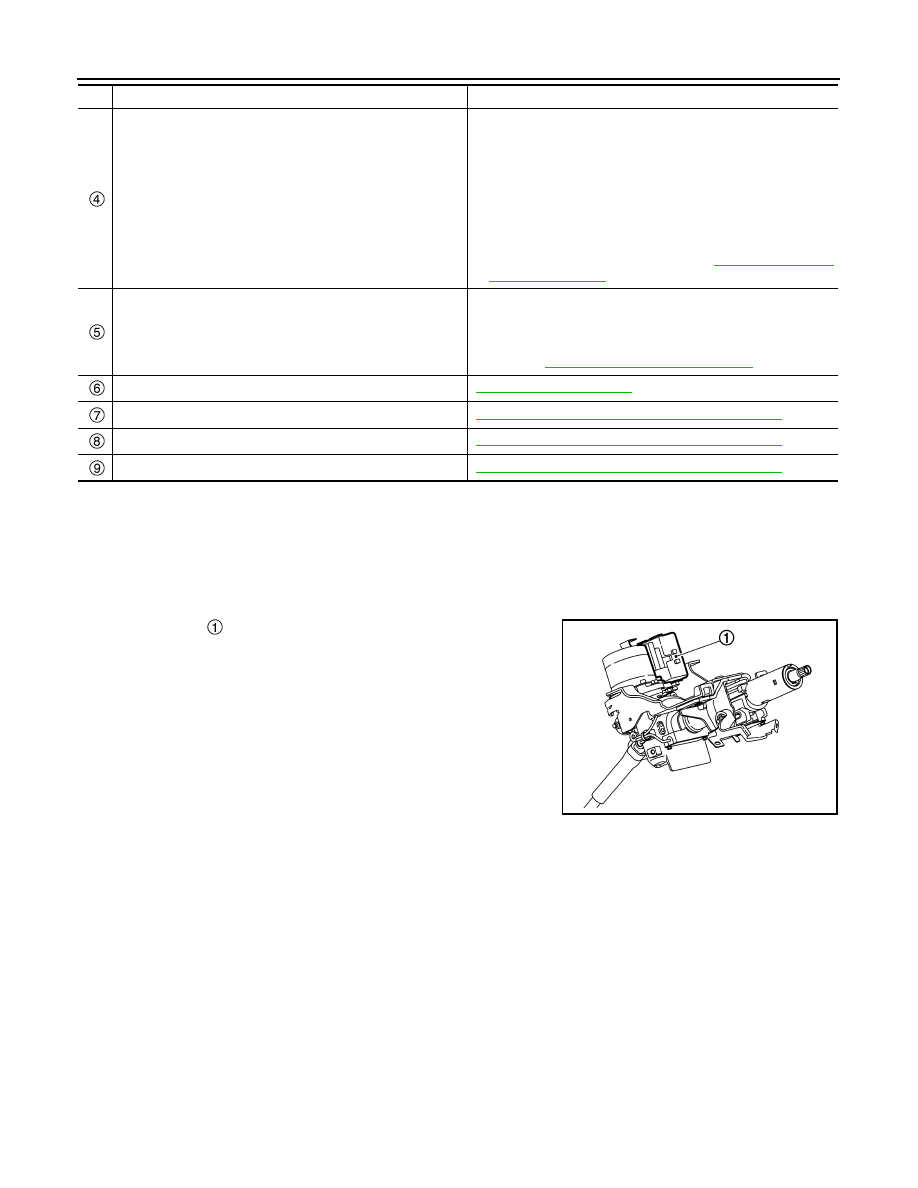
EPS Control Unit
INFOID:0000000010688400
NOTE:
The EPS control unit, EPS motor, torque sensor, and reduction gear are integrated with the steering column
assy.
• EPS control unit
is installed to steering column assembly.
• EPS control unit performs an arithmetical operation on data, such
as steering wheel turning force (sensor signal) from the torque
sensor, vehicle speed signal, etc. Then it generates an optimum
assist torque signal to the EPS motor according to the driving con-
dition.
• EPS control unit decreases the output signal to EPS motor while
extremely using the power steering function (e.g., full steering)
consecutively for protecting EPS motor and EPS control unit
(Overload protection control).
• When the stop/start system operation starts, the EPS control unit
receives a stop/start status signal from ECM via CAN communica-
tion and disables the assist control. (Models with stop/start system)
• When the driver turns the steering wheel (torque application exceeding the specified torque) during stop/
start system operation, the EPS control unit transmits an EPS torque signal to ECM via CAN communication
and restarts the engine (disables stop/start system). (Models with stop/start system)
• EPS control unit receives a Park Assist status signal from the around view monitor control unit and performs
around view monitor with park assist control.
• EPS control unit receives a Park Assist status signal to the around view monitor control unit to examine
whether the EPS control unit can perform around view monitor with park assist control or not.
• Around view monitor with park assist control is cancelled when the driver operates the steering wheel during
around view monitor with park assist control.
• Diagnoses can be performed with CONSULT.
EPS Motor, Torque Sensor, Reduction Gear
INFOID:0000000010688401
NOTE:
The EPS control unit, EPS motor, torque sensor, and reduction gear are integrated with the steering column
assy.
Around view monitor control unit
*2
• Transmits mainly the following signal to EPS control unit via
CAN communication.
- Park Assist status signal
- Park Assist malfunction signal
- Steering angle command signal
• Receives mainly the following signal to EPS control unit via
CAN communication.
- EPS torque signal
- Park Assist permit signal
• For detailed installation location, refer to
.
Sonar control unit
*2
• Transmits mainly the following signals to EPS control unit via
CAN communication.
- Steering angle command signal
• For detailed installation location,
: Refer to
SN-119, "Component Parts Location"
.
EPS control unit
EPS motor
STC-10, "EPS Motor, Torque Sensor, Reduction Gear"
Torque sensor
STC-10, "EPS Motor, Torque Sensor, Reduction Gear"
Reduction gear
STC-10, "EPS Motor, Torque Sensor, Reduction Gear"
No.
Component
Function
JSGIA1430ZZ