содержание .. 1544 1545 1546 1547 ..
Nissan X-Trail 32. Manual - part 1546
LU-20
< PRECAUTION >
[QR25DE]
PRECAUTIONS
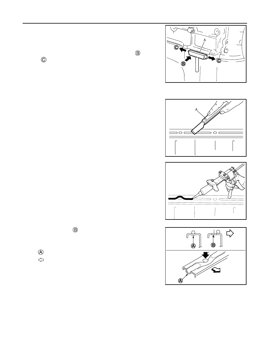
• After removing mounting nuts and bolts, separate the mating sur-
face using the seal cutter [SST: KV10111100] (A) and remove old
liquid gasket sealing.
CAUTION:
Never damage the mating surfaces.
• Tap the seal cutter [SST: KV10111100] to insert it
, and then
slide it
by tapping on the side as shown in the figure.
• In areas where the seal cutter [SST: KV10111100] is difficult to use,
lightly tap the parts using a plastic hammer to remove it.
CAUTION:
If for some unavoidable reason tool such as a screwdriver is
used, be careful not to damage the mating surfaces.
LIQUID GASKET APPLICATION PROCEDURE
1.
Using a scraper (A), remove old liquid gasket adhering to the liq-
uid gasket application surface and the mating surface.
• Remove liquid gasket completely from the groove of the liquid
gasket application surface, mounting bolts, and bolt holes.
2.
Wipe the liquid gasket application surface and the mating sur-
face with white gasoline (lighting and heating use) to remove
adhering moisture, grease and foreign materials.
3.
Attach liquid gasket tube to the tube presser (commercial ser-
vice tool).
Use Genuine Liquid Gasket or equivalent.
4.
Apply liquid gasket without gaps to the specified location accord-
ing to the specified dimensions.
• If there is a groove for liquid gasket application, apply liquid
gasket to the groove.
• As for bolt holes
, normally apply liquid gasket inside the
holes. Occasionally, it should be applied outside the holes.
Check to read the text of this manual.
• Within five minutes of liquid gasket application, install the mat-
ing component.
• If liquid gasket protrudes, wipe it off immediately.
• Do not retighten mounting bolts or nuts after the installation.
• After 30 minutes or more have passed from the installation, fill
engine oil and engine coolant.
CAUTION:
If there are specific instructions in this manual, observe them.
JPBIA0052ZZ
JPBIA0053ZZ
EMA0622D
: Groove
: Inside
JPBIA0010ZZ