Nissan X-Trail 32. Manual - part 1019


  Главная      Nissan     Nissan X-Trail 32 - Service Manual


поиск по сайту            


содержание   ..  1017  1018  1019  1020   ..


Nissan X-Trail 32. Manual - part 1019


LOW PRESSURE FUEL PUMP

EC-1205

< DTC/CIRCUIT DIAGNOSIS >

[R9M]

C

D

E

F

G

H

I

J

K

L

M

A

EC

N

P

O

LOW PRESSURE FUEL PUMP

Component Function Check

INFOID:0000000010935912

1.

CHECK FUEL PUMP FUNCTION

1.

Turn ignition switch ON.

2.

Pinch fuel feed hose with two fingers.
NOTE:
Fuel pressure pulsation should be felt on the fuel feed hose for 1 second after ignition switch is turned ON.

Is the inspection result normal?

YES

>> INSPECTION END

NO

>>

EC-1205, "Diagnosis Procedure"

.

Diagnosis Procedure

INFOID:0000000010935913

1.

CHECK FPCM POWER SUPPLY CIRCUIT

1.

Turn ignition switch OFF.

2.

Disconnect FPCM harness connector.

3.

Turn ignition switch ON.

4.

Check the voltage between FPCM harness connector and ground.

Is the inspection result normal?

YES

>> GO TO 2.

NO

>> Perform the trouble diagnosis for power supply circuit. Refer to 

EC-963, "ECM : Diagnosis Proce-

dure"

.

2.

CHECK FPCM GROUND CIRCUIT

1.

Turn ignition switch OFF.

2.

Check the continuity between FPCM harness connector and ground.

Is the inspection result normal?

YES

>> GO TO 3.

NO

>> Repair open circuit or short to power in harness or connectors.

3.

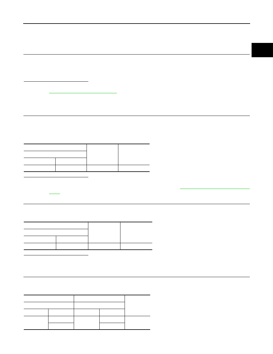
CHECK FPCM INPUT AND OUTPUT CIRCUIT

1.

Disconnect ECM harness connector.

2.

Check the continuity between FPCM harness connector and ECM harness connector.

3.

Also check harness for short to ground and to power.

+

Voltage

FPCM

Connector

Terminal

B132

8

Ground

Battery voltage

+

Continuity

FPCM

Connector

Terminal

B132

7

Ground

Existed

+

Continuity

FPCM

ECM

Connector

Terminal

Connector

Terminal

B133

9

E79

20

Existed

10

22

EC-1206

< DTC/CIRCUIT DIAGNOSIS >

[R9M]

LOW PRESSURE FUEL PUMP

Is the inspection result normal?

YES

>> GO TO 4.

NO

>> Repair or replace error-detected parts.

4.

CHECK FUEL PUMP CONTROL CIRCUIT

1.

Disconnect fuel level sensor unit and fuel pump (main) harness connector.

2.

Check the continuity between FPCM harness connector and fuel level sensor unit and fuel pump (main)
harness connector.

3.

Also check harness for short to ground and to power.

Is the inspection result normal?

YES

>> GO TO 5.

NO

>> Repair or replace error-detected parts.

5.

CHECK LOW PRESSURE FUEL PUMP

Refer to 

EC-1206, "Component Inspection (Low Pressure Fuel Pump)"

.

Is the inspection result normal?

YES

>> Replace FPCM.

NO

>> Replace low pressure fuel pump.

Component Inspection (Low Pressure Fuel Pump)

INFOID:0000000010935914

1.

CHECK FUEL PRESSURE REGULATOR

1.

Turn ignition switch OFF.

2.

Check low fuel pressure.

Is inspection result normal?

YES

>> INSPECTION END

NO

>> GO TO 2.

2.

CHECK LOW PRESSURE FUEL PUMP

1.

Turn ignition switch OFF.

2.

Disconnect fuel level sensor unit and fuel pump (main).

3.

Check resistance between fuel level sensor unit and fuel pump (main) terminals as follows.

Is the inspection result normal?

YES

>> INSPECTION END

NO

>> Replace fuel level sensor unit and fuel pump (main).

+

Continuity

FPCM

Fuel level sensor unit and fuel 

pump (main)

Connector

Terminal

Connector

Terminal

B131

3

B130

1

Existed

4

4

5

3

6

2

+

Continuity

Fuel level sensor unit and 

fuel pump (main)

Terminals

2

3

Existed

4

BRAKE SWITCH

EC-1207

< DTC/CIRCUIT DIAGNOSIS >

[R9M]

C

D

E

F

G

H

I

J

K

L

M

A

EC

N

P

O

BRAKE SWITCH

Component Function Check

INFOID:0000000010935915

1.

CHECK BRAKE SWITCH FUNCTION

1.

Turn ignition switch ON.

2.

Check the voltage between ECM harness connector terminals as per the following.

Is the inspection result normal?

YES

>> INSPECTION END

NO

>> Proceed to 

EC-1207, "Diagnosis Procedure"

.

Diagnosis Procedure

INFOID:0000000010935916

1.

CHECK BRAKE SWITCH POWER SUPPLY CIRCUIT

1.

Turn ignition switch OFF.

2.

Disconnect stop lamp switch harness connector.

3.

Check the voltage between stop lamp switch harness connector and ground.

M/T models

CVT models

Is the inspection result normal?

YES

>> GO TO 2.

NO

>> Perform the trouble diagnosis for power supply circuit.

2.

CHECK BRAKE SWITCH INPUT SIGNAL CIRCUIT

1.

Disconnect ECM harness connector.

2.

Check the continuity between stop lamp switch harness connector and ECM harness connector.

M/T models

ECM

Condition

Voltage

(Approx.)

Connector

+

Terminal

E79

16

1

Brake pedal

Slightly de-
pressed

0 V

Fully released

Battery voltage

+

Voltage

Stop lamp switch

Connector

Terminal

E121

3

Ground

Battery voltage

+

Voltage

Brake pedal position switch

Connector

Terminal

E112

1

Ground

Battery voltage

+

Continuity

Stop lamp switch

ECM

Connector

Terminal

Connector

Terminal

E121

4

E79

16

Existed

EC-1208

< DTC/CIRCUIT DIAGNOSIS >

[R9M]

BRAKE SWITCH

CVT models

3.

Also check harness for short to ground and to power.

Is the inspection result normal?

YES

>> GO TO 3.

NO

>> Repair or replace error-detected parts.

3.

CHECK BRAKE SWITCH

Check the brake switch. Refer to 

EC-1208, "Component Inspection (Stop Lamp Switch)"

 (M/T models), 

EC-

1208, "Component Inspection (Brake Pedal Position Switch)"

 (CVT models).

Is the inspection result normal?

YES

>> Check intermittent incident. Refer to 

GI-44, "Intermittent Incident"

.

NO

>> Replace stop lamp switch.

Component Inspection (Stop Lamp Switch)

INFOID:0000000010935917

1.

CHECK STOP LAMP SWITCH-1

1.

Turn ignition switch OFF.

2.

Disconnect stop lamp switch harness connector.

3.

Check the continuity between stop lamp switch terminals as per the following conditions.

Is the inspection result normal?

YES

>> INSPECTION END

NO

>> GO TO 2.

2.

CHECK STOP LAMP SWITCH-2

1.

Adjust stop lamp switch installation. Refer to 

BR-11, "Inspection and Adjustment"

 (LHD models) or 

BR-75,

"Inspection and Adjustment"

 (RHD models).

2.

Check the continuity between stop lamp switch terminals as per the following conditions.

Is the inspection result normal?

YES

>> INSPECTION END

NO

>> Replace stop lamp switch.

Component Inspection (Brake Pedal Position Switch)

INFOID:0000000010935918

1.

CHECK BRAKE PEDAL POSITION SWITCH-1

1.

Turn ignition switch OFF.

+

Continuity

Brake pedal position switch

ECM

Connector

Terminal

Connector

Terminal

E112

2

E79

16

Existed

Stop lamp switch

Condition

Continuity

+

-

Terminals

3

 4

Brake pedal

Fully released

Existed

Slightly de-
pressed

Not existed

Stop lamp switch

Condition

Continuity

+

-

Terminals

3

 4

Brake pedal

Fully released

Existed

Slightly de-
pressed

Not existed


содержание   ..  1017  1018  1019  1020   ..