Nissan Qashqai J11. Manual - part 881


  Index      Nissan     Nissan Qashqai J11 - Service and Repair Manual


Search            


Content   ..  879  880  881  882   ..


Nissan Qashqai J11. Manual - part 881


WT-70

< PERIODIC MAINTENANCE >

[WITHOUT TPMS]

ROAD WHEEL

PERIODIC MAINTENANCE

ROAD WHEEL

Inspection

INFOID:0000000010380607

APPEARANCE

Road Wheel

• Check road wheel for deformation, cracks, corrosion and other damage.
• Check wheel nuts for looseness by using torque wrench.

Tire

• Check entire circumference and both sides of each tire for deformation, cracks, scratch and other damage.
• Check tire tread for wear and foreign matter such as nails and small rock.
• Check that tire pressure is the specified value.

Wheel Balance Adjustment (Aluminum Wheel)

INFOID:0000000010380608

PREPARATION BEFORE ADJUSTMENT

Using releasing agent, remove double-faced adhesive tape from the road wheel.

CAUTION:

• Never scratch the road wheel during removal.
• After removing double-faced adhesive tape, wipe clean traces of releasing agent from the road

wheel.

ADJUSTMENT

• The details of the adjustment procedure are different for each model of wheel balancer. Therefore, refer to

each instruction manual. 

• If a tire balance machine has adhesion balance weight mode settings and drive-in weight mode setting,

select and adjust a drive-in weight mode suitable for aluminum wheels.

1.

Set road wheel on tire balance machine using the center hole as a guide. Start the tire balance machine.
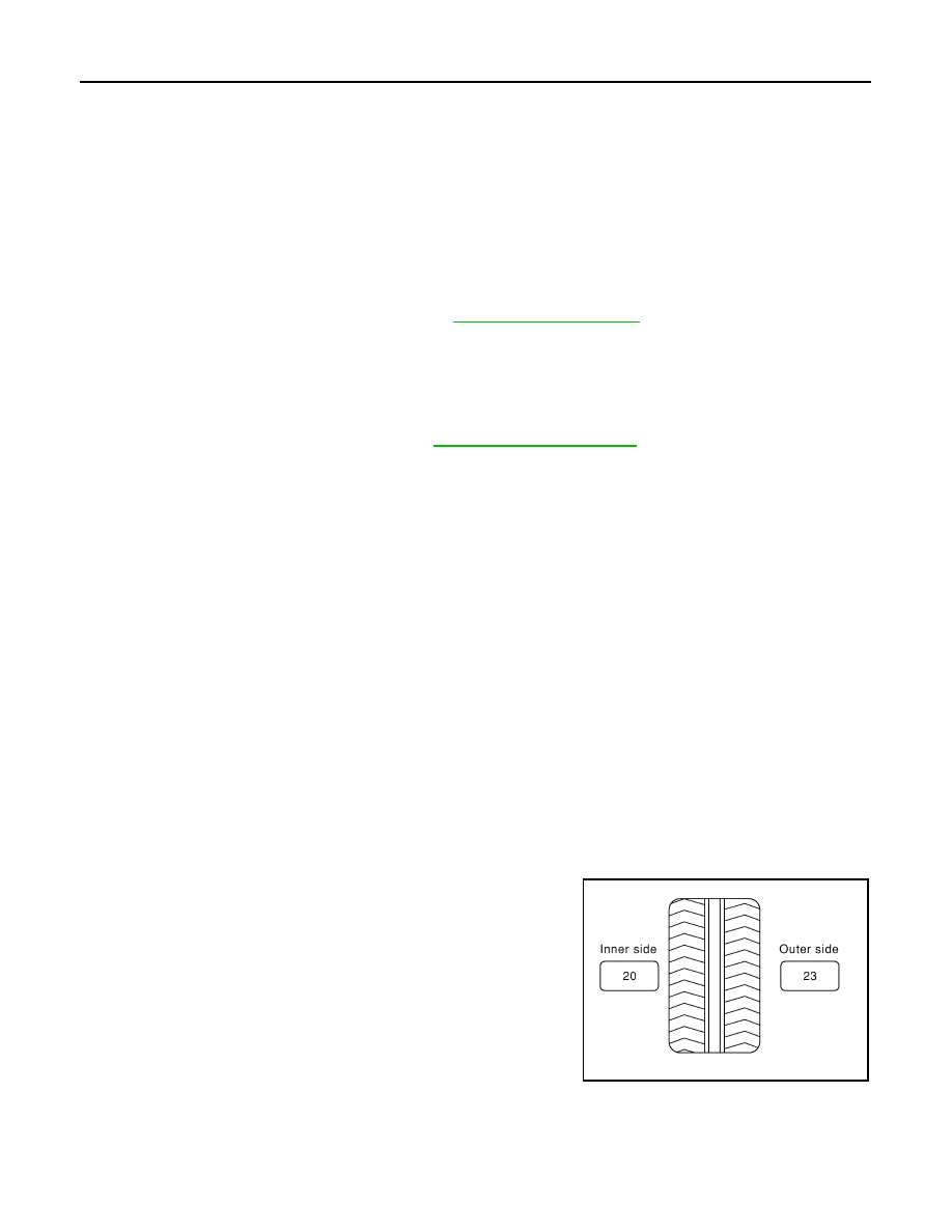
2.

When inner and outer unbalance values are shown on the tire balance machine indicator, multiply outer
unbalance value by 5/3 to determine balance weight that should be used. Select the outer balance weight
with a value closest to the calculated value above and install to the designated outer position of, or at the
designated angle in relation to the road wheel.

CAUTION:

• Never install the inner balance weight before installing the outer balance weight.
• Before installing the balance weight, always to clean the mating surface of the road wheel.

a.

Indicated unbalance value 

×

 5/3 = balance weight to be installed

Calculation example:
23 g (0.81 oz) 

×

 5/3 = 38.33 g (1.35 oz) 

 40 g (1.41 oz) bal-

ance weight (closer to calculated balance weight value)
NOTE:
Note that balance weight value must be closer to the calculated
balance weight value.
Example:
37.4 

 35 g (1.23 oz)

37.5 

 40 g (1.41 oz)

b.

Installed balance weight in the position.

Wheel nut tightening torque

: Refer to 

WT-73, "Exploded View"

.

Tire pressure

: Refer to 

WT-75, "Tire Air Pressure"

.

SMA054D

ROAD WHEEL

WT-71

< PERIODIC MAINTENANCE >

[WITHOUT TPMS]

C

D

F

G

H

I

J

K

L

M

A

B

WT

N

O

P

• When installing balance weight (1) to road wheels, set it into

the grooved area (A) on the inner wall of the road wheel as
shown in the figure so that the balance weight center (B) is
aligned with the tire balance machine indication position
(angle) (C).

CAUTION:

• Always use genuine NISSAN balance weights.
• Balance weights are non-reusable; always replace with

new ones.

• Never install three or more sheets of balance weight.

c.

If calculated balance weight value exceeds 50 g (1.76 oz), install
two balance weight sheets in line with each other as shown in
the figure.

CAUTION:

Never install one balance weight sheet on top of another.

3.

Start the tire balance machine again.

4.

Install drive-in balance weight on inner side of road wheel in the tire balance machine indication position
(angle).

CAUTION:

Never install three or more balance weight.

5.

Start the tire balance machine. Check that the inner and outer residual unbalance value is within the
allowable unbalance value.

CAUTION:

If either residual unbalance value exceeds limit, repeat installation procedures.

Wheel Balance Adjustment (Steel Wheel)

INFOID:0000000010380609

PREPARATION BEFORE ADJUSTMENT

Remove balance weight from the road wheel.

CAUTION:

Never scratch the road wheel during removal.

ADJUSTMENT

JPEIC0040ZZ

PEIA0033E

Allowable unbalance value

Dynamic (At flange)

: Refer to 

WT-75, "Road Wheel"

.

Static (At flange)

: Refer to 

WT-75, "Road Wheel"

.

WT-72

< PERIODIC MAINTENANCE >

[WITHOUT TPMS]

ROAD WHEEL

• The details of the adjustment procedure are different for each model of wheel balancer. Therefore, refer to

each instruction manual. 

• If a tire balance machine has adhesion balance weight mode settings and drive-in weight mode setting,

select and adjust a drive-in weight mode suitable for steel wheels.

1.

Set road wheel to wheel balancer, and then start wheel balancer. 

2.

Install balance weight to road wheel according to the unbalance and position (angle) displayed on wheel
balancer. 

CAUTION:

• Always use genuine NISSAN balance weights.
• Balance weights are non-reusable; always replace with new ones.
• Always use a plastic hammer when attaching the weight. 
• Never install three or more balance weights on one side. 

3.

Start the tire balance machine. Check that the inner and outer residual unbalance value is within the
allowable unbalance value.

CAUTION:

If either residual unbalance value exceeds limit, repeat installation procedures.

Tire Rotation

INFOID:0000000010380610

• Follow the maintenance schedule for tire rotation service intervals.

Refer to 

MA-6, "General Maintenance"

.

• When installing the wheel, tighten wheel nuts to the specified

torque. Refer to 

WT-73, "Exploded View"

.

CAUTION:

• Never include the T-type spare tire when rotating the tires.
• When installing wheels, tighten them diagonally by dividing

the work two to three times in order to prevent the wheels
from developing any distortion.

• Never tighten wheel nut at torque exceeding the criteria.
• Use NISSAN genuine wheel nut.

Allowable unbalance value

Dynamic (At flange)

: Refer to 

WT-75, "Road Wheel"

.

Static (At flange)

: Refer to 

WT-75, "Road Wheel"

.

SMA829C

ROAD WHEEL TIRE ASSEMBLY

WT-73

< REMOVAL AND INSTALLATION >

[WITHOUT TPMS]

C

D

F

G

H

I

J

K

L

M

A

B

WT

N

O

P

REMOVAL AND INSTALLATION

ROAD WHEEL TIRE ASSEMBLY

Exploded View

INFOID:0000000010380612

Removal and Installation

INFOID:0000000010377981

REMOVAL

1.

Remove wheel nuts.

2.

Remove tire assembly.

INSTALLATION

Install in the reverse order of removal.

Inspection

INFOID:0000000010380613

1.

Check tires for wear and improper inflation.

2.

Check wheels for deformation, cracks and other damage. If deformed, remove wheel and check wheel
runout.

a.

Remove tire from aluminum wheel and mount on a tire balance machine.

b.

Set dial indicator as shown in the figure.

c.

Check runout, if the axial runout (A) or radial runout (B) exceeds
the limit, replace aluminum wheel.

How to Handle Puncture Repair Agent (With Puncture Repair Kit)

INFOID:0000000010494017

CAUTION:

• Never spill the sealant in the tire during repair.
• If the sealant spills, wipe it out with a waste cloth.

1.

Tire assembly

: N·m (kg-m, ft-lb)

E1EIA0119GB

Limit

Axial runout (A)

: Refer to 

WT-75, "Road Wheel"

.

Radial runout (B)

: Refer to 

WT-75, "Road Wheel"

.

SEIA0737E


Content   ..  879  880  881  882   ..