Nissan Qashqai J11. Manual - part 812
DLN-164
< UNIT DISASSEMBLY AND ASSEMBLY >
[TRANSFER: TY30A]
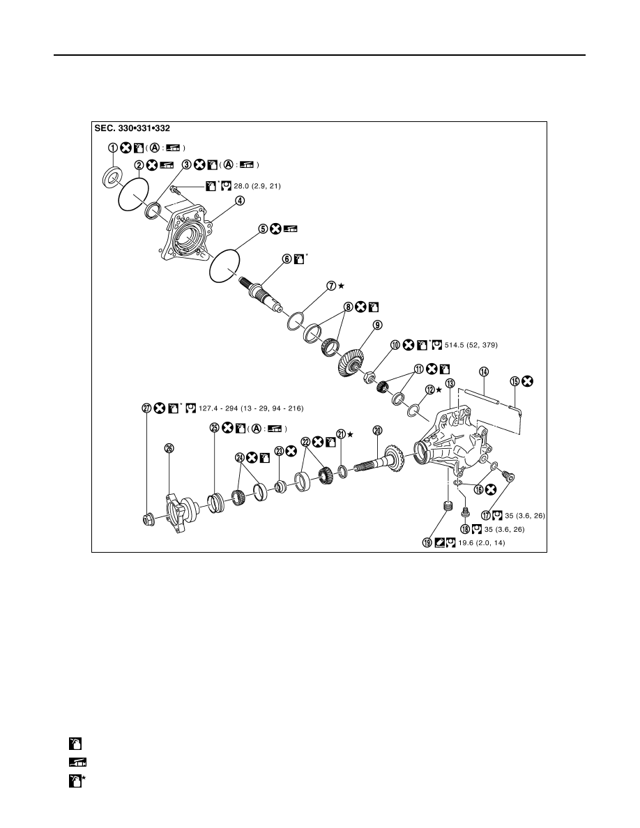
DRIVE PINION
DRIVE PINION
Exploded View
INFOID:0000000010288363
1.
Adapter case oil seal (outer)
2.
O-ring (outer)
3.
Adapter case oil seal (inner)
4.
Adapter case
5.
O-ring (inner)
6.
Ring gear shaft
7.
Ring gear adjusting shim
(adapter case side)
8.
Ring gear shaft bearing
(adapter case side)
9.
Ring gear
10. Ring gear nut
11.
Ring gear shaft bearing
(transfer case side)
12. Ring gear adjusting shim
(transfer case side)
13. Transfer case
14. Air breather hose
15. Air breather tube
16. Gasket
17. Filler plug
18. Drain plug
19. Plug
20. Drive pinion
21. Drive pinion adjusting shim
22. Drive pinion bearing (front side)
23. Collapsible spacer
24. Drive pinion bearing (rear side)
25. Drive pinion oil seal
26. Companion flange
27. Lock nut
A: Oil seal lip
: Apply gear oil.
: Apply multi-purpose grease.
: Apply anti-corrosive oil.
JSDIA0319GB