Nissan Qashqai J11. Manual - part 483
DIAGNOSIS SYSTEM (ECM)
EC9-87
< SYSTEM DESCRIPTION >
[R9M]
C
D
E
F
G
H
I
J
K
L
M
A
EC9
N
P
O
SWIRL THROTTLE
POSITION SET-
POINT USED BY
THE MONITORING
SYSTEM
—
—
—
EGR BP VALVE
CONTROL SET-
POINT USED BY
THE MONITORING
SYSTEM
—
—
—
ET THROTTLE PO-
SITION USED BY
THE MONITORING
SYSTEM
—
—
—
TURBO WATER
COOLING PUMP
COMMAND
—
—
—
EGR COOLING BY-
PASS PWM COM-
MAND
—
—
—
EGR VALVE POSI-
TION SETPOINT
—
—
—
INLET THROTTLE
POSITION SET-
POINT
—
—
—
BOOST PRESURE
PWM COMMAND
—
—
—
FLOW WATER
VALVE COMMAND
OF WATER SYS-
TEM
—
—
—
WIRE PTC3 ORDER
—
—
—
WIRE PTC2 ORDER
—
—
—
WIRE PTC1 ORDER
—
—
—
HEATING GLOW
PLUGS PWM COM-
MAND
—
—
—
IDLE ENGINE
SPEED SETPOINT
—
—
—
AIR CONDITION-
ING STATE
—
—
—
THERMOPLUNG-
ERS COMMAND
STATE
—
—
—
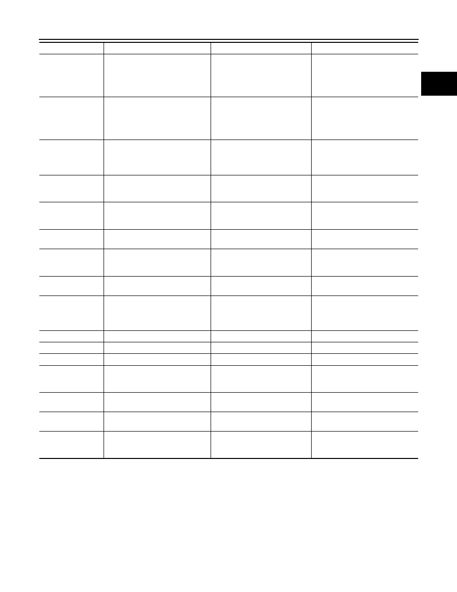
Test item
Condition
Judgment
Check item (Remedy)