Nissan Qashqai J11. Manual - part 373
 

  Index      Nissan     Nissan Qashqai J11 - Service and Repair Manual


Search            


Content   ..  371  372  373  374   ..


Nissan Qashqai J11. Manual - part 373


ECK-52

< SYSTEM DESCRIPTION >

[K9K]

DIAGNOSIS SYSTEM (ECM)

DIAGNOSIS SYSTEM (ECM)

CONSULT Function

INFOID:0000000010289666

FUNCTION

*: The following emission-related diagnostic information is cleared when the ECM memory is erased.

• Diagnostic trouble codes

SELF-DIAGNOSTIC MODE

Self Diagnostic Item

Regarding items detected in “SELF-DIAG RESULTS” mode, refer to — 

ECK-97, "DTC Index"

.

How to erase DTC

• If power is continuously in the ON position after a DTC is detected, turn power switch OFF before turning

power switch to the ON position again, and then erase DTC.

• Check the all self-diagnostic screen to confirm there are no DTCs in other ECUs.

Freeze Frame Data and 1st Trip Freeze Frame Data

The Freeze Frame Data shows the state of the vehicle at the time a DTC is detected and is useful in re-creat-
ing the circumstances that caused the malfunction.
NOTE:
The following table includes information (items) in applicable to this vehicle. For information (items) applicable
to this vehicle, refer to CONSULT display items.

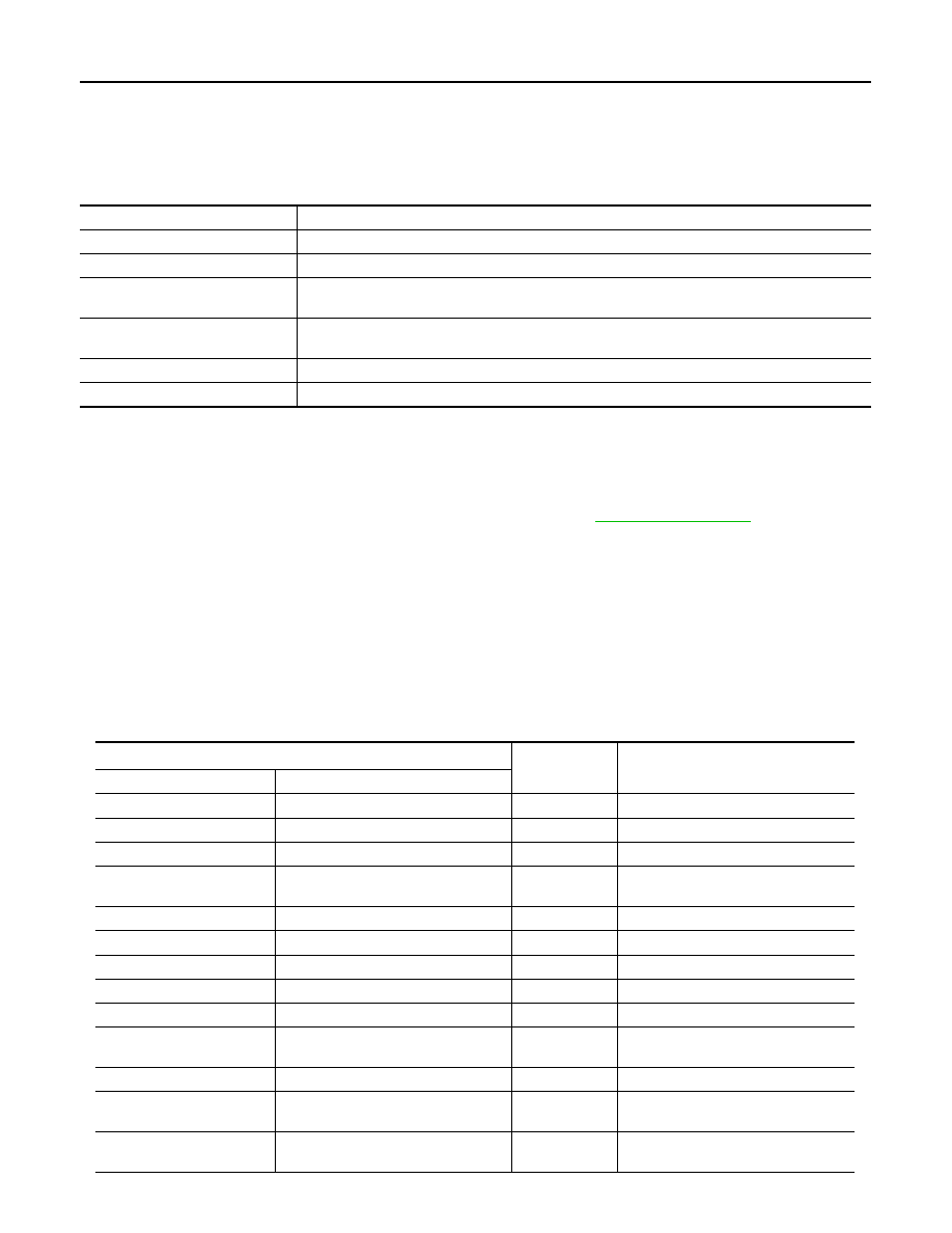
Diagnostic test mode

Function

Self-diagnostic results

Self-diagnostic results such as DTC can be read and erased quickly.*

Data monitor

Input/Output data in the ECM can be read.

Work support

This mode enables a technician to adjust some devices faster and more accurately by following 
the indications on the CONSULT unit.

Active test

Diagnostic Test Mode in which CONSULT drives some actuators apart from the ECMs and also 
shifts some parameters in a specified range.

ECU identification

ECM part number and homologation number can be read.

Configuration

This function is used to store vehicle specifications to ECM after ECM replacement.

Item

*

Unit

Remarks

CONSULT screen terms

Full spell

WATER TEMP

Water temperature

°

C or 

°

F

ENGINE SPEED

Engine speed

rpm

VEHICLE SPEED

Vehicle speed

km/h or mph

COMPUTER SUPPLY 
VOLTAGE

Computer supply voltage

V

RAIL PRES SET

Rail pressure setting

bar

RAIL PRESSURE

Rail pressure

bar

RAIL PRESS SEN VOLT

Rail pressure sensor voltage

V

FUEL FLOW

Fuel flow

mg/cp

BOOST PRESSURE

Boost pressure

mbar

BOOST PRESS REF VAL-
UE

Boost pressure reference value

hpa

MEASURE AIR FLOW

Measured air flow

kg/h

TURBOCHARGING SOLE-
NOID VALVE OCR

Turbocharging solenoid valve OCR

%

DAMPER VALVE UP-
STREAM TEMPERATURE

Estimated inlet flap upstream tempera-
ture

°

C or 

°

F

DIAGNOSIS SYSTEM (ECM)

ECK-53

< SYSTEM DESCRIPTION >

[K9K]

C

D

E

F

G

H

I

J

K

L

M

A

ECK

N

P

O

MANIFOLD PRESSURE

Manifold pressure

mbar

INLET AIR TEMPERATURE

Inlet air temperature

°

C or 

°

F

EST. AIR FLOW

Estimated air flow

mg/cp

INLET AIR FLOW

Inlet air flow

mg/cp

ATMOSPHERIC PRES-
SURE

Atmospheric pressure

mbar

TBN UPSTR PRS SEN 
VOLT

Turbine upstream pressure sensor 
voltage

V

AIR INLET/F REL POS

Air inlet flap relative position

%

FUEL TEMPERATURE

Fuel temperature

°

C or 

°

F

IN FLAP ABSO POSI

Air inlet flap absolute position

%

INLET/F SEN SUPPLY 
VOLT

Inlet flap sensor supply voltage

mV

DAMPER VALVE SEN 
VOLT

Damper valve sensor voltage

mV

DMPR VLV SET POS

Damper valve setpoint position

%

IN/FLAP CTRL

Inlet flap control

%

SEN 1 FEED V

Sensors No. 1 feed voltage

mV

ADDITIONAL INFO FD9C

Additional information FD9C

ALTERNATOR LOAD

Alternator load

%

ADDITIONAL INFO 2069

Additional information 2069

Nm

SEN 2 FEED V

Sensors No. 2 feed voltage

mV

PL PTNMR T2 V

Pedal potentiometer track 2 voltage

mV

PL PTNMR T1 V

Pedal potentiometer track 1 voltage

mV

HEATER PLUG CONTROL

Heater plug control

%

EGR VALVE OPENING 
REFERENCE

EGR valve opening reference

%

EGR VALVE CONTROL

EGR valve control

%

LAST EGR VALVE OFFSET

Last EGR valve offset

%

EGR VALVE FIRST OFF-
SET

EGR valve first offset

%

POTN VAL EGR VALVE 
CLSD

Potentiometer value EGR valve closed

%

EGR SENSOR SUPPLY 
VOLTAGE

EGR sensor supply voltage

mV

EGR POTENTIOMETER 
VOLTAGE

EGR potentiometer voltage

mV

EXHAUST SYSTEM FLOW

Exhaust system flow

g/s

ADDITIONAL INFORMA-
TION 24F3

Additional information 24F3

°

C or 

°

F

TEMP. UPSTREAM OF PF

Temperature upstream of particle filter

°

C or 

°

F

PRS UPSTR OF TBN

Pressure upstream of turbine

mbar

RFRG TEMP PRESS SEN 
VOLT

Refrigerant pressure sensor voltage

V

REFRIGERANT PRES-
SURE

Refrigerant pressure

bar

Item

*

Unit

Remarks

CONSULT screen terms

Full spell

ECK-54

< SYSTEM DESCRIPTION >

[K9K]

DIAGNOSIS SYSTEM (ECM)

TBN UPSTR TEMP SETP

Turbine upstream temperature set-
point

°

C or 

°

F

TEMP UPSTREAM TUR-
BINE

Temperature upstream of turbine

°

C or 

°

F

RV/LV BUTTON VOLTAGE

RV/LV button voltage

mV

LAST OFF/V CLOSE

Last offset damper valve closed

%

LAST OFF/V OPEN

Last offset damper valve open

%

SEN SUPPLY N-3 VOL

Sensor supply No. 3 voltage

mV

SUPPLY VOLTAGE EX-
HAUST AIR FLAP SENSOR

Supply voltage exhaust air flap sensor

mV

FIRST OFFSET OF THE 
CLOSED EXHAUST FLAP

First offset of the closed exhaust flap

%

EGR LOW PRESSURE PO-
SITION

EGR low pressure position

%

LAST OFFSET OF 
CLOSED LOW PRESSURE 
EGR

Last offset of closed low pressure EGR

%

EGR LOW PRESSURE 
OCR

EGR low pressure OCR

%

LOW PRESSURE EGR PO-
SITION REFERENCE VAL-
UE

Low pressure EGR position reference 
value

%

L/PRES EGR VALVE POSI-
TION

Low pressure EGR valve position

%

LOW PRESSURE EGR 
VALVE SUPPLY VOLTAGE

Low pressure EGR valve supply volt-
age

mV

LOW PRESSURE EGR 
VALVE FIRST OFFSET

Low pressure EGR valve first offset

%

PART.FILTER UPSTREAM 
TEMP SENSOR VOLTAGE

Part.filter upstream temperature sen-
sor voltage

 V

ADDITIONAL INFO 2813

Additional information 2813

°

Crk

POST INJECTION FLOW

Post injection flow

mg/cp

POST INJECTION FLOW 1

Post injection flow 1

mg/cp

FLOW GAS IN DPF

Flow of gas inside the particle filter

m3/h

P/FLT DIFF. PRS

Particle filter pressure diff

hPa

REGEN MALFNC

Number of regeneration failure

FIRST OFF/V CLOSE

First offset damper valve closed

%

FIRST OFF/V OPEN

First offset damper valve open

%

ATMOS PRESS SEN VOLT

Atmospheric pressure sensor voltage

mV

OIL DILUTION INFORMA-
TION

Oil dilution information

%

RAIL FLOW REGULATION 
VALVE OCR

Rail flow regulation valve OCR

%

CRNKS SYNC LOSS COUN

Crankshaft synchronisation loss 
counter

AVERAGE PERIOD OF 
FLOWMETER SIGNAL

Average period of flowmeter signal

µ

S

F/FLOW CORR CYL NO.1

Fuel flow correction for cylinder No.1

F/FLOW CORR CYL NO.2

Fuel flow correction for cylinder No.2

Item

*

Unit

Remarks

CONSULT screen terms

Full spell

DIAGNOSIS SYSTEM (ECM)

ECK-55

< SYSTEM DESCRIPTION >

[K9K]

C

D

E

F

G

H

I

J

K

L

M

A

ECK

N

P

O

F/FLOW CORR CYL NO.3

Fuel flow correction for cylinder No.3

F/FLOW CORR CYL NO.4

Fuel flow correction for cylinder No.4

ADDITIONAL INFORMA-
TION FD1A

Additional information FD1A

µ

F

ADDITIONAL INFORMA-
TION FD19

Additional information FD19

µ

F

ADDITIONAL INFORMA-
TION FD1B

Additional information FD1B

µ

F

ADDITIONAL INFORMA-
TION FD1C

Additional information FD1C

µ

F

CYLINDER 1 ADAPTATION 
STATUS

Cylinder 1 adaptation status

CYLINDER 2 ADAPTATION 
STATUS

Cylinder 2 adaptation status

CYLINDER 3 ADAPTATION 
STATUS

Cylinder 3 adaptation status

CYLINDER 4 ADAPTATION 
STATUS

Cylinder 4 adaptation status

MEDIAN OF TEMPERA-
TURES WHOSE SENSORS 
ARE LIABLE TO RATIO-
NALITY DIAGNOSIS

Median of temperatures whose sen-
sors are liable to rationality diagnosis

°

C or 

°

F

ADDITIONAL INFO 24D0

Additional information 24D0

BRAKE CNT 1 DURATION

Brake contact 1 duration

S

BRAKE CNT 2 DURATION

Brake contact 2 duration

S

OIL TEMPERATURE - EN-
GINE

Oil temperature - engine

°

C or 

°

F

ENGINE RPM

Engine rpm

rpm

VEHICLE SPEED DIS-
PLAYED

Vehicle speed displayed

km/h or mph

ADDITIONAL INFO 287A

Additional information 287A

ADDITIONAL INFORMA-
TION FD42

Additional information FD42

ADDITIONAL INFORMA-
TION FD43

Additional information FD43

ADDITIONAL INFORMA-
TION FD4D

Additional information FD4D

ADDITIONAL INFORMA-
TION FD4E

Additional information FD4E

MAIN INJECTION FLOW

Main injection flow

 mg/cp

LOADED NOx mass

Loaded nox mass

 G

CUMULATIVE MILEAGE IN 
HIGHWAY CONDITIONS

Cumulative mileage in highway condi-
tions

km or mile

ADDITIONAL INFO FD2D

Additional information FD2D

%

ADDITIONAL INFO FD2F

Additional information FD2F

mg/cp

ADDITIONAL INFO FD96

Additional information FD96

µ

F

ADDITIONAL INFO FD2E

Additional information FD2E

rpm

SOOT IN P/FLT

Soot in the particle filter

G

EXH THROTTLE POSITION

Exhaust throttle position

%

Item

*

Unit

Remarks

CONSULT screen terms

Full spell


Content   ..  371  372  373  374   ..