Nissan Qashqai J11. Manual - part 365
 

  Index      Nissan     Nissan Qashqai J11 - Service and Repair Manual


Search            


Content   ..  363  364  365  366   ..


Nissan Qashqai J11. Manual - part 365


ECK-20

< SYSTEM DESCRIPTION >

[K9K]

COMPONENT PARTS

periodically. DPF can be effective for a long time through the cycle of trapping particulate matter and regener-
ation.

Exhaust Gas Pressure Sensor

INFOID:0000000010289608

Exhaust gas pressure sensor measures exhaust gas pressure around turbocharger outlet, converts it to volt-
age signal and transmits it to ECM. ECM controls turbocharger boost pressure according to this signal.

DPF Differential Pressure Sensor

INFOID:0000000010289609

DPF differential pressure sensor is connected to diesel particulate filter with exhaust pressure tube. DPF dif-
ferential pressure sensor measures the exhaust back pressure before the filter. It converts into a voltage sig-
nal. ECM receives the signal and estimates the amount of particulate matter in diesel particulate filter.

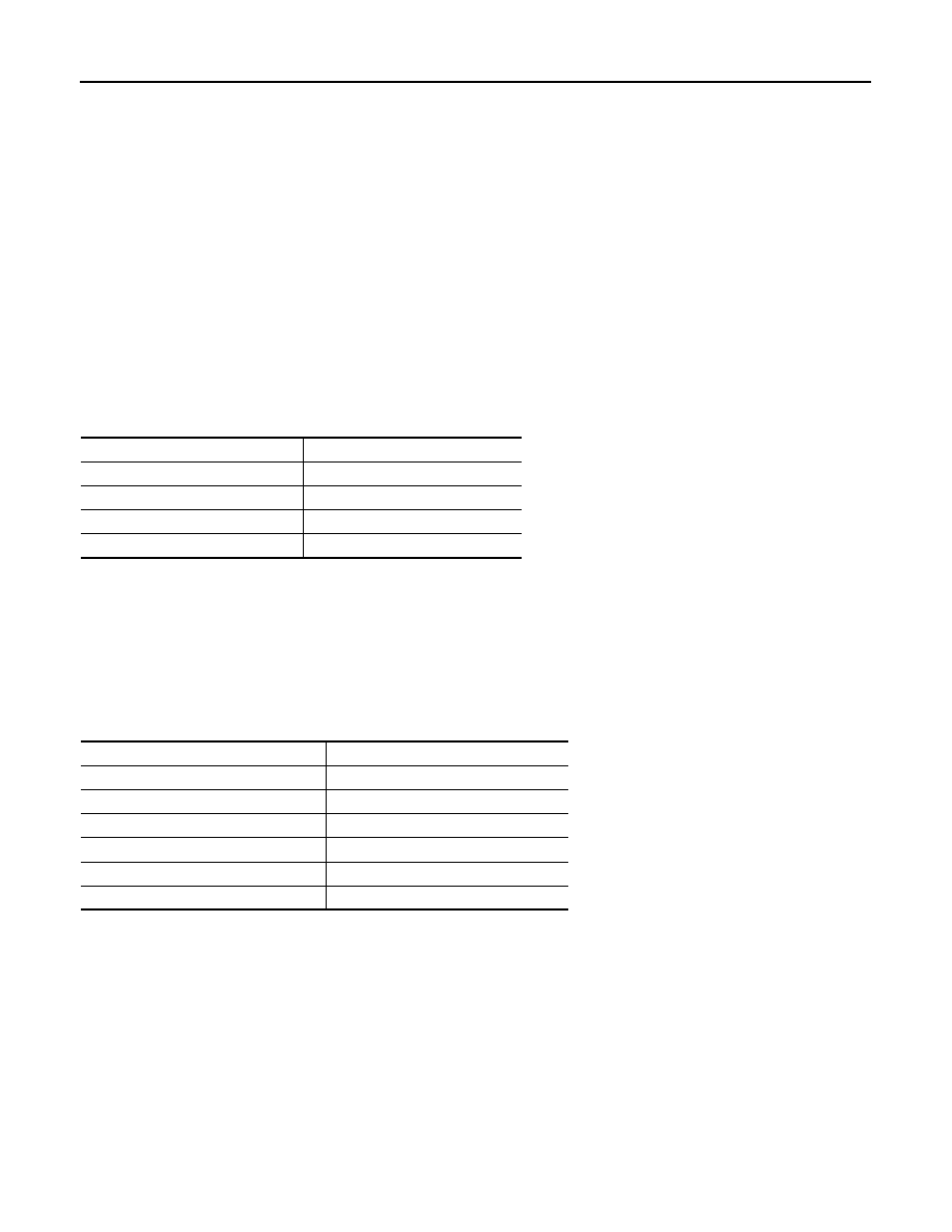
Exhaust Gas Temperature Sensor 1

INFOID:0000000010289610

The exhaust gas temperature (EGT) sensor is built-into the Exhaust Pressure Sensor. The sensor detects the
exhaust gas temperature before turbocharger. The sensor modifies a voltage signal from the ECM. The modi-
fied signal returns to the ECM as the exhaust gas temperature input. 

<Reference data>

Exhaust Gas Temperature Sensor 2

INFOID:0000000010289611

The exhaust gas temperature sensor 2 is used to detect the exhaust gas temperature after oxidation catalyst.
The sensor modifies a voltage signal from the ECM. The modified signal returns to the ECM as the exhaust
gas temperature input. The sensor uses a thermistor which is sensitive to the change in temperature. The
electrical resistance of the thermistor decreases as temperature increases.

<Reference data>

Glow Control Unit

INFOID:0000000010289612

When ignition switch is turned ON while cooling temperature is lower than the specified value, ECM actuates
glow plug through glow relay. Because of this, combustion chamber is warmed and stabilized combustion at
starting can be obtained under low cooling temperature. The preheating time is determined according to cool-
ing temperature, inlet air temperature and battery voltage.

Glow Plug

INFOID:0000000010289613

The glow plug is located in the cylinder head, in order to stabilize combustion and keep good cold start perfor-
mance.
The glow plug glows in response to a signal sent from the ECM, allowing current to flow through the glow plug
via the glow control unit.

Exhaust gas temperature

°

C (

°

F)

Resistance (Approx.)

k

0 (32)

5.671 – 6.118

25 (77)

1.99 – 2.123

100 (212)

0.097 – 0.103

130 (266)

0.087 – 0.091

Exhaust gas temperature

°

C (

°

F)

Resistance

k

20 (68)

89.309 - 159.795

100 (212)

22.96 - 51.16

300 (572)

2.261 - 2.975

500 (932)

0.640 - 0.709

600 (1112)

0.406 - 0.442

750 (1382)

0.230 - 0.254

COMPONENT PARTS

ECK-21

< SYSTEM DESCRIPTION >

[K9K]

C

D

E

F

G

H

I

J

K

L

M

A

ECK

N

P

O

Glow Indicator Lamp

INFOID:0000000010289614

Glow indicator lamp illuminates when glow system is activated in order to inform it to the driver.

Cooling Fan

INFOID:0000000010289615

Cooling fan operates at each speed when the current flows in the cooling fan motor as follows.
Refer to 

ECK-34, "COOLING FAN CONTROL : System Description"

 for cooling fan operation.

Cooling Fan Resistor

INFOID:0000000010503739

Cooling Fan Resister is installed to the power circuit of Cooling Fan Motor and switches cooling fan speed
between LOW and HIGH.
When Cooling Fan Motor is rotated at LOW speeds, power is supplied to the cooling fan via Cooling Fan
Resistor.

Thermoplunger Unit

INFOID:0000000010289616

Thermoplunger Unit is installed to the passage of engine coolant and has four thermoplungers. These ther-
moplungers increase engine coolant temperature by the passage of electric current through the Ther-
moplunger Control Unit.

Thermoplunger Control Unit

INFOID:0000000010289617

Thermoplunger Control Unit passes a current to Thermoplungers according to a signal transmitted from ECM.

Accelerator Pedal Position Sensor

INFOID:0000000010289620

The accelerator pedal position (APP) sensor is installed on the upper
end of the accelerator pedal assembly. The sensors detect the
accelerator pedal position and sends a signal to the ECM. The ECM
uses the signal to determine the amount of fuel to be injected.

Refrigerant Pressure Sensor 

INFOID:0000000010289621

The refrigerant pressure sensor is installed at the liquid tank of the air conditioner system. The sensor is used
to sense a refrigerant pressure.

Stop Lamp Switch

INFOID:0000000010289622

Stop lamp switch is installed to brake pedal bracket. Stop lamp switch signal is sent to ECM via CAN commu-
nication from BCM when the brake pedal is depressed. This signal is used mainly to decrease the engine
speed when the vehicle is being driven.

Clutch Interlock Switch & Clutch Pedal Position Switch

INFOID:0000000010501742

Clutch interlock switch and clutch pedal position switch are installed to clutch pedal bracket.
ECM detects the state of the clutch pedal by those two types of input signal (ON/OFF).

PBIB1741E

Clutch pedal

Clutch interlock switch

Clutch pedal position switch

Released

OFF

ON

Depressed

ON

OFF

ECK-22

< SYSTEM DESCRIPTION >

[K9K]

COMPONENT PARTS

ASCD Steering Switch

INFOID:0000000010289624

ASCD steering switch has variant values of electrical resistance for each button. ECM reads voltage variation
of switch, and determines which button is operated.

Malfunction Indicator Lamp

INFOID:0000000010289626

The malfunction indicator Lamp (MIL) is located on the combination
meter. The MIL will illuminate when the ignition switch is turned ON
without the engine running (bulb check).
When the engine is started, the MIL should turn OFF. If the MIL
remains illuminated, the on board diagnostic system has detected an
engine system malfunction.

Information Display

INFOID:0000000010289627

The operation mode of the ASCD and speed limiter are indicated on the information display in the combination
meter.
ECM transmits the status signal to the combination meter via CAN communication according to ASCD and
speed limiter operation.

DC/DC Converter

INFOID:0000000010289629

The DC/DC converter is installed at the behind of the glove box
assembly and supplies power to the electrical equipment.
This converter is connected to ECM via the engine communication
line and includes an internal voltage converter. When restarting the
vehicle from the stop/start system operating condition, the voltage
converter boosts the voltage conveyed from the battery and provides
stable power to the electrical equipment to prevent reset from occur-
ring. For further details, refer to 

ECK-39, "STOP/START SYSTEM :

System Description"

.

Engine Restart Relay

INFOID:0000000010289630

The engine restart relay is installed in the relay box and controlled by ECM when restarting the engine during
the stop/start system operation.

Engine Restart Bypass Control Relay

INFOID:0000000010289631

The engine restart bypass control relay is controlled by ECM and controls the engine restart bypass relay.

Engine Restart Bypass Relay

INFOID:0000000010289632

The engine restart bypass relay reduces battery voltage drop right
after the starter motor activation at an engine restart by switching the
electric circuit of the starter motor. For details, refer to 

ECK-39,

"STOP/START SYSTEM : System Description"

.

JPNIA1882ZZ

JSBIA4574ZZ

JSBIA1994ZZ

COMPONENT PARTS

ECK-23

< SYSTEM DESCRIPTION >

[K9K]

C

D

E

F

G

H

I

J

K

L

M

A

ECK

N

P

O

Hood Switch

INFOID:0000000010289637

Hood switch is located around radiator core support. Hood switch detects open/close condition of hood and
input the hood switch signal to IPDM E/R.

Stop/Start Indicator Lamp

INFOID:0000000010289638

The stop/start indicator lamp is located on the combination meter.
The stop/start indicator lamp turns ON when the stop/start system is
operating.
When a malfunction is detected in the stop/start system, the stop/
start indicator lamp blinks at a slow speed to alert the driver to the
malfunction. When a driver

s operation is judged as dangerous one

during stop/start system operation, the stop/start indicator lamp
blinks at a high speed.
When ECM detects a malfunction in the stop/start system compo-
nents, the lamp activation request signal is transmitted to ECM via
CAN communication. ECM transmits the stop/start indicator lamp
signal to the combination meter. Based on the signal from ECM, the
combination meter turns blinks stop/start indicator lamp to inform the driver that a malfunction has been
detected.
NOTE:
• If the stop/start indicator lamp does not turn ON during stop/start system operation, check the stop/start indi-

cator lamp circuit. Refer to 

ECK-385, "Component Function Check"

.

• If the stop/start indicator lamp turns blinks continuously, stop/start system-related DTC or malfunction is

detected. Perform total self-diagnosis and inspect or repair the unit.

Stop/start indicator lamp status

*: Engine is stalled after alert for 1.5 seconds.

Stop/Start OFF Switch

INFOID:0000000010289639

The stop/start OFF switch is mounted on the switch panel of the
driver side lower instrument panel. When the stop/start OFF switch
is pressed, the indicator lump turns ON and the stop/start system
can be deactivated.
For further details, refer to 

ECK-49, "STOP/START SYSTEM :

Switch Name and Function"

.

Fuel Heater With Water In Fuel Level Sensor

INFOID:0000000010289641

• Water in fuel sensor detects the water volume increasing in the fuel filter.
• When water increases in the fuel filter, ECM turns ON the fuel filter warning lamp, according to the signal

from water in fuel sensor.

JPBIA4266ZZ

System condition

Condition

Stop/start indicator lamp

Warning chime

Operate

Normal

Illuminate

Door (driver side) open 
and seat belt released

High speed blinking

Sound

Hood open

High speed blinking

*

Sound

*

Fail-Safe

Starter motor operation 
counter: too much

Slow speed blinking

Malfunction of stop/start 
system

Slow speed blinking

JSBIA4078ZZ


Content   ..  363  364  365  366   ..