Nissan Qashqai J11. Manual - part 2195


  Index      Nissan     Nissan Qashqai J11 - Service and Repair Manual


Search            


Content   ..  2193  2194  2195  2196   ..


Nissan Qashqai J11. Manual - part 2195


DAS-194

< DTC/CIRCUIT DIAGNOSIS >

[DRIVER ASSISTANCE SYSTEM]

WASHER PUMP CIRCUIT

WASHER PUMP CIRCUIT

Component Function Check

INFOID:0000000010690627

1.

CHECK WASHER PUMP CIRCUIT

1.

Turn ignition switch ON.

2.

Select “WASH ACTIVE” of “AVM” with CONSULT.

3.

Check operation while operating the test item.

Is the inspection result normal?

YES

>> Washer pump circuit is normal.

NO

>> Refer to 

DAS-194, "Diagnosis Procedure"

.

Diagnosis Procedure

INFOID:0000000010690628

1.

CHECK WASHER PUMP POWER SUPPLY CIRCUIT

1.

Turn ignition switch OFF.

2.

Disconnect washer pump connector.

3.

Turn ignition switch ON.

4.

Select “WASH ACTIVE” of “AVM” with CONSULT.

5.

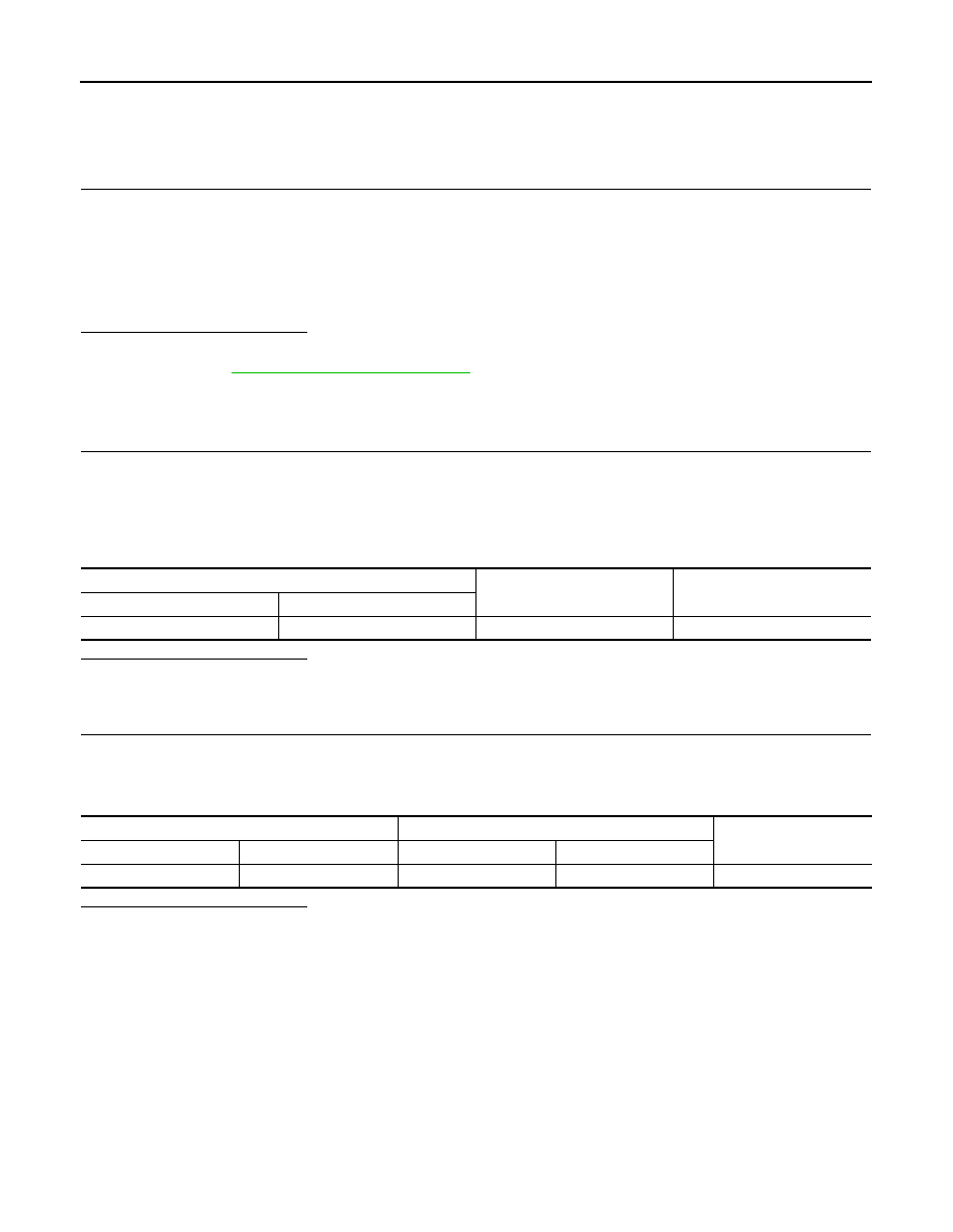
Check voltage between washer pump connector and ground.

Is the inspection result normal?

YES

>> GO TO 2.

NO

>> Repair or replace harness or connector.

2.

CHECK WASHER PUMP GROUND CIRCUIT

1.

Turn ignition switch OFF.

2.

Disconnect pump control unit connector.

3.

Check continuity between washer pump connector and pump control unit connector.

Is the inspection result normal?

YES

>> Replace washer pump.

NO

>> Repair or replace harness or connector.

On

: Washer pump is activated.

Off

: Washer pump is not activated.

Washer pump

Ground

Voltage

Connector

Terminal

E46

2

Battery voltage

Washer pump

Pump control unit

Continuity

Connector

Terminal

Connector

Terminal

E46

1

B78

3

Existed

DAS

DRIVER ASSISTANCE SYSTEM SYMPTOMS

DAS-195

< SYMPTOM DIAGNOSIS >

[DRIVER ASSISTANCE SYSTEM]

C

D

E

F

G

H

I

J

K

L

M

B

N

P

A

SYMPTOM DIAGNOSIS

DRIVER ASSISTANCE SYSTEM SYMPTOMS

Symptom Table

INFOID:0000000010416937

LANE DEPARTURE WARNING SYSTEM SYMPTOMS

BLIND SPOT WARNING SYSTEM SYMPTOMS

Symptom

Possible cause

Inspection item/Reference page

Indicator/warning lamps do not 
illuminate when ignition switch 
OFF 

 ON

LDW warning lamp does not 
illuminate.

• Combination meter
• Front camera unit

Combination meter.
Refer to 

MWI-29, "CONSULT 

Function (METER/M&A)"

.

Front camera unit.
Refer to 

DAS-39, "CONSULT 

Function (LANE CAMERA)"

.

LDW ON indicator does not 
illuminate.

• Combination meter
• Front camera unit

All of indicator/warning 
lamps does not illuminate.
• LDW warning lamp
• LDW ON indicator

• Power supply and ground cir-

cuit of front camera unit

• Combination meter
• Front camera unit
• Harness

Power supply and ground circuit 
of front camera unit.
Refer to 

DAS-191, "FRONT 

CAMERA UNIT : Diagnosis Pro-
cedure"

.

LDW system is not activated.

LDW warning lamp is not 
turned ON 

 OFF.

• Combination meter
• Front camera unit
• Sonar control unit

LDW system setting can not be 
turned ON/OFF on the informa-
tion display.
Refer to 

DAS-198, "Diagnosis 

Procedure"

.

Warning buzzer is not 
sounding.

• Warning buzzer
• Front camera unit

Warning buzzer circuit.
Refer to 

DAS-193, "Component 

Function Check"

.

LDW functions are not timely

• Front camera calibration
• Front camera unit

Front camera aiming adjust-
ment.
Refer to 

DAS-98, "Work Proce-

dure (Camera Aiming Adjust-
ment)"

.

Symptom

Possible cause

Inspection item/Reference page

Indicator/warning lamps do not il-
luminate when ignition switch 
OFF 

 ON.

BSW warning lamp does not 
illuminate

• Combination meter
• Around view monitor control 

unit

Combination meter. Refer to 

MWI-29, "CONSULT Function 
(METER/M&A)"

.

Around view monitor control unit. 
Refer to 

DAS-33, "CONSULT 

Function"

.

BSW ON indicator does not 
illuminate

• Combination meter
• Around view monitor control 

unit

All of indicator/warning 
lamps do not illuminate;
• BSW warning lamp
• BSW ON indicator

• Power supply and ground cir-

cuit of around view monitor 
control unit

• Around view monitor control 

unit

• Combination meter

Power supply and ground circuit 
of around view monitor control 
unit. Refer to 

DAS-189, 

"AROUND VIEW MONITOR 
CONTROL UNIT : Diagnosis 
Procedure"

.

BSW indicator does not turn 
ON

• Harness between around 

view monitor control unit and 
BSW indicator

• Around view monitor control 

unit

• BSW indicator

Around view monitor control unit. 
Refer to 

DAS-33, "CONSULT 

Function"

.

DAS-196

< SYMPTOM DIAGNOSIS >

[DRIVER ASSISTANCE SYSTEM]

DRIVER ASSISTANCE SYSTEM SYMPTOMS

MOVING OBJECT DETECTION SYSTEM SYMPTOMS

TRAFFIC SIGN RECOGNITION SYSTEM SYMPTOMS

BSW system is not activated.

BSW warning lamp is not 
turned ON 

 OFF

Around view monitor control unit

BSW system setting cannot be 
turned ON/OFF on the informa-
tion display.
Refer to 

DAS-198, "Diagnosis 

Procedure"

.

Warning buzzer is not sound-
ing

• Warning buzzer
• Around view monitor control 

unit

Warning buzzer circuit.
Refer to 

DAS-193, "Component 

Function Check"

.

BSW functions are not timely

• Rear camera calibration
• Rear camera
• Around view monitor control 

unit

Rear camera calibration.
Refer to 

DAS-104, "Work Proce-

dure (Rear Camera Calibration)"

.

Rear camera washer is not activated

• Washer pump
• Pump control unit

Washer pump circuit.
Refer to 

DAS-194, "Component 

Function Check"

.

Rear camera wash is insufficient

• Washer tube (include check 

valve)

• Air tube
• Washer/Air nozzle

Rear view camera washer/air 
blower function inspection.
Refer to 

DAS-104, "Work Proce-

dure (Rear Camera Calibration)"

.

Symptom

Possible cause

Inspection item/Reference page

Symptom

Possible cause

Inspection item/Reference page

Indicator/warning lamps do not 
illuminate when ignition switch 
OFF 

 ON

MOD warning lamp does not 
illuminate.

• Combination meter
• Around view monitor control 

unit

Combination meter.
Refer to 

MWI-29, "CONSULT 

Function (METER/M&A)"

.

Around view monitor control 
unit.
Refer to 

DAS-33, "CONSULT 

Function"

.

MOD ON indicator does not 
illuminate.

• Combination meter
• Around view monitor control 

unit

All of indicator/warning 
lamps does not illuminate.
• MOD warning lamp
• MOD ON indicator

• Power supply and ground cir-

cuit of around view monitor 
control unit

• Around view monitor control 

unit

Power supply and ground circuit 
of around view monitor control 
unit.
Refer to 

DAS-189, "AROUND 

VIEW MONITOR CONTROL 
UNIT : Diagnosis Procedure"

.

MOD system is not activated.

MOD warning lamp is not 
turned ON 

 OFF.

Around view monitor control 
unit

MOD system setting can not be 
turned ON/OFF on the informa-
tion display.
Refer to 

DAS-198, "Diagnosis 

Procedure"

.

Warning buzzer is not 
sounding.

• Warning buzzer
• Around view monitor control 

unit

Warning buzzer circuit.
Refer to 

DAS-193, "Component 

Function Check"

.

MOD functions are not timely

• Rear camera calibration
• Rear camera
• Around view monitor control 

unit

Rear camera calibration.
Refer to 

DAS-104, "Work Proce-

dure (Rear Camera Calibra-
tion)"

.

Rear camera washer is not activated

• Washer pump
• Pump control unit

washer pump circuit.
Refer to 

DAS-194, "Component 

Function Check"

.

Rear camera wash is insufficient

• Washer tube (include check 

valve)

• Air  tube
• Washer/Air nozzle

Rear view camera washer/air 
blower function inspection.
Refer to 

DAS-83, "Inspection 

Procedure"

.

DAS

DRIVER ASSISTANCE SYSTEM SYMPTOMS

DAS-197

< SYMPTOM DIAGNOSIS >

[DRIVER ASSISTANCE SYSTEM]

C

D

E

F

G

H

I

J

K

L

M

B

N

P

A

DRIVER ATTENTION ALERT SYSTEM SYMPTOMS

Symptom

Possible cause

Inspection item/Reference page

Indicator/warning lamps do not 
illuminate when ignition switch 
OFF 

 ON

TSR warning lamp does not 
illuminate.

• Combination meter
• Front camera unit

Combination meter.
Refer to 

MWI-29, "CONSULT 

Function (METER/M&A)"

.

Front camera unit.
Refer to 

DAS-39, "CONSULT 

Function (LANE CAMERA)"

.

TSR ON indicator does not 
illuminate.

• Combination meter
• Front camera unit

All of indicator/warning 
lamps does not illuminate.
• TSR  warning  lamp
• TSR  ON  indicator

• Power supply and ground cir-

cuit of front camera unit

• Combination meter
• Front camera unit
• Harness

Power supply and ground circuit 
of front camera unit.
Refer to 

DAS-191, "FRONT 

CAMERA UNIT : Diagnosis Pro-
cedure"

.

TSR system is not activated.

TSR warning lamp is not 
turned ON 

 OFF.

Front camera unit

TSR system setting can not be 
turned ON/OFF on the informa-
tion display.
Refer to 

DAS-198, "Diagnosis 

Procedure"

.

TSR functions are not timely

• Front camera aiming adjust-

ment

• Front camera unit

Front camera aiming adjust-
ment.
Refer to 

DAS-98, "Work Proce-

dure (Camera Aiming Adjust-
ment)"

.

Symptom

Possible cause

Inspection item/Reference page

Indicator/warning lamps do not 
illuminate when ignition switch 
OFF 

 ON

DAA warning lamp does not 
illuminate.

• Combination meter
• Around view monitor control 

unit

Combination meter.
Refer to 

MWI-29, "CONSULT 

Function (METER/M&A)"

.

Around view monitor control 
unit.
Refer to 

DAS-33, "CONSULT 

Function"

.

DAA ON indicator does not 
illuminate.

• Combination meter
• Around view monitor control 

unit

All of indicator/warning 
lamps does not illuminate.
• DAA warning lamp
• DAA ON indicator

• Power supply and ground cir-

cuit of around view monitor 
control unit

• Around view monitor control 

unit

Power supply and ground circuit 
of around view monitor control 
unit.
Refer to 

DAS-189, "AROUND 

VIEW MONITOR CONTROL 
UNIT : Diagnosis Procedure"

.

DAA system is not activated.

DAA warning lamp is not 
turned ON 

 OFF.

Around view monitor control 
unit

DAA system setting can not be 
turned ON/OFF on the informa-
tion display.
Refer to 

DAS-198, "Diagnosis 

Procedure"

.

Warning buzzer is not 
sounding.

• Warning buzzer
• Around view monitor control 

unit

Warning buzzer circuit.
Refer to 

DAS-193, "Component 

Function Check"

.


Content   ..  2193  2194  2195  2196   ..