Content .. 2181 2182 2183 2184 ..
Nissan Qashqai J11. Manual - part 2183
DAS-146
< DTC/CIRCUIT DIAGNOSIS >
[DRIVER ASSISTANCE SYSTEM]
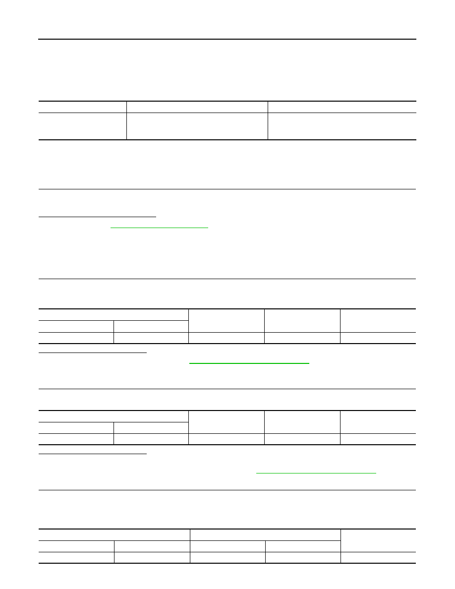
U1302 CAMERA POWER VOLT
U1302 CAMERA POWER VOLT
DTC Logic
INFOID:0000000010416878
DTC DETECTION LOGIC
Diagnosis Procedure
INFOID:0000000010416879
WITH PUMP CONTROL UNIT
1.
CHECK AVM CAMERA DATA MONITOR ITEMS
Check “F-CAMERA IMAGE SIGNAL”, “REAR CAMERA IMAGE SIGNAL”, “DR-SIDE CAMERA IMAGE SIG”
and “PA-SIDE CAMERA IMAGE SIG” in “DATA MONITOR” of “AVM” using CONSULT.
Is “OK” displayed for all cameras?
YES
>> Refer to
GI-41, "Intermittent Incident"
.
NO-1 (Front camera)>>GO TO 2.
NO-2 (Rear camera)>>GO TO 5.
NO-3 (Side camera LH)>>GO TO 8.
NO-4 (Side camera RH)>>GO TO 11.
2.
CHECK FRONT CAMERA POWER SUPPLY (CAMERA)
1.
Turn ignition switch ON.
2.
Check voltage between front camera connector and ground.
Is the inspection result normal?
YES
>> Replace front camera. Refer to
AV-268, "Removal and Installation"
.
NO
>> GO TO 3.
3.
CHECK FRONT CAMERA POWER SUPPLY (AROUND VIEW MONITOR CONTROL UNIT)
Check voltage between around view monitor control unit connector and ground.
Is the inspection result normal?
YES
>> GO TO 4.
NO
>> Replace around view monitor control unit. Refer to
AV-267, "Removal and Installation"
4.
CHECK FRONT CAMERA POWER SUPPLY CIRCUIT CONTINUITY
1.
Turn ignition switch OFF.
2.
Disconnect around view monitor control unit connector and front camera connector.
3.
Check continuity between around view monitor control unit connector and front camera connector.
CONSULT Display
DTC Detection Condition
Possible Cause
CAMERA POWER VOLT
[U1302]
Short in camera power supply circuit.
• Harness or connectors.
• Camera.
• Around view monitor control unit.
Front camera
Ground
Condition
Voltage
(Approx.)
Connector
Terminal
E106
2
—
CAMERA switch is ON.
6.0 V
Around view monitor control unit
Ground
Condition
Voltage
(Approx.)
Connector
Terminal
M8
68
—
CAMERA switch is ON.
6.0 V
Around view monitor control unit
Front camera
Continuity
Connector
Terminal
Connector
Terminal
M8
68
E106
2
Existed