Content .. 2042 2043 2044 2045 ..
Nissan Qashqai J11. Manual - part 2044
WCS-24
< ECU DIAGNOSIS INFORMATION >
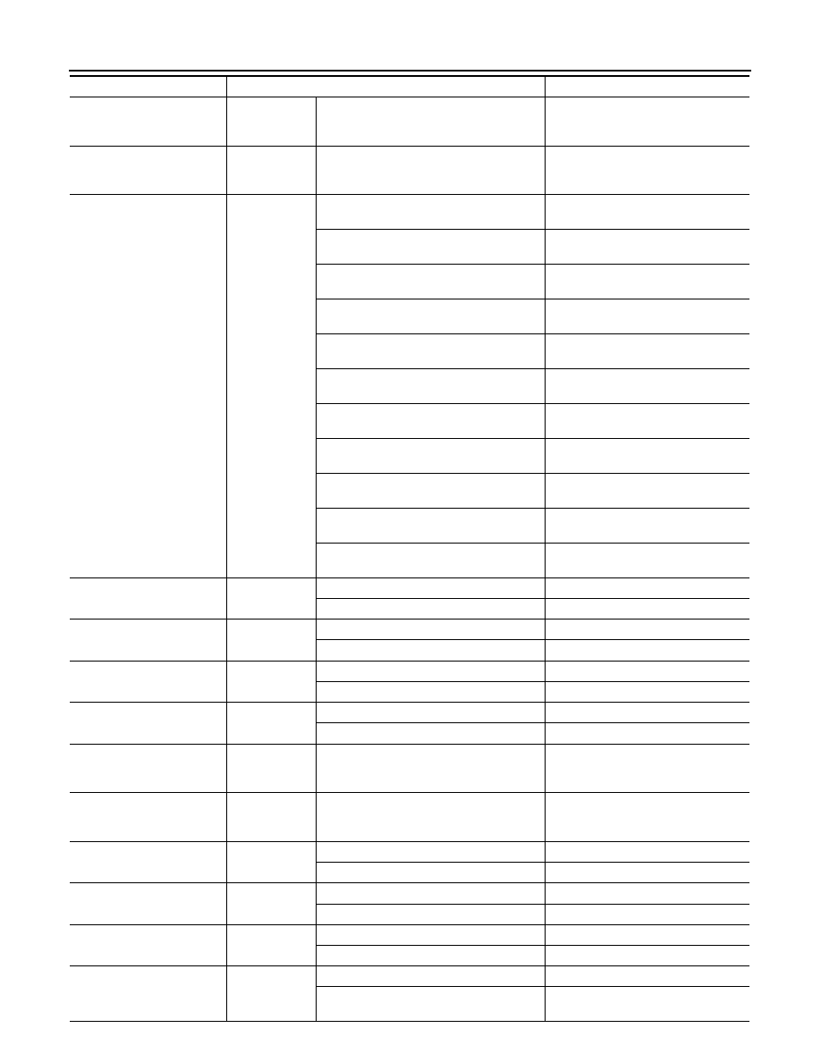
COMBINATION METER
DPF W/L
Engine running
NOTE:
This item is displayed, but cannot be moni-
tored.
Off
TRAILER IND
Ignition switch
ON
NOTE:
This item is displayed, but cannot be moni-
tored.
Off
SHIFT IND
Ignition switch
ON
During the indication of “P” by shift position
indicator
P
During the indication of “R” by shift position
indicator
R
During the indication of “N” by shift position
indicator
N
During the indication of “D” by shift position
indicator
D
During the indication of “L” by shift position
indicator
L
During the indication of “M1” by shift posi-
tion indicator
M1
During the indication of “M2” by shift posi-
tion indicator
M2
During the indication of “M3” by shift posi-
tion indicator
M3
During the indication of “M4” by shift posi-
tion indicator
M4
During the indication of “M5” by shift posi-
tion indicator
M5
During the indication of “M6” by shift posi-
tion indicator
M6
M RANGE SW
Ignition switch
ON
Selector lever in manual mode position
On
Other than the above
Off
NM RANGE SW
Ignition switch
ON
Selector lever in manual mode position
Off
Other than the above
On
AT SFT UP SW
Ignition switch
ON
Selector lever in + position
On
Other than the above
Off
AT SFT DWN SW
Ignition switch
ON
Selector lever in – position
On
Other than the above
Off
A/C LOW TEMP
Ignition switch
ON
NOTE:
This item is displayed, but cannot be moni-
tored.
Off
COMP F/B SIG
Ignition switch
ON
NOTE:
This item is displayed, but cannot be moni-
tored.
Off
PKB SW
Ignition switch
ON
Parking brake switch ON
On
Parking brake switch OFF
Off
BUCKLE SW
Ignition switch
ON
Driver seat belt not fastened
On
Driver seat belt fastened
Off
BRAKE OIL SW
Ignition switch
ON
Brake fluid level switch ON
On
Brake fluid level switch OFF
Off
AMB POWER
Ignition switch
ON
Other than the following
On
Receives A/C auto amp. connection recog-
nition signal
Off
Monitor Item
Condition
Value/Status