Content .. 2031 2032 2033 2034 ..
Nissan Qashqai J11. Manual - part 2033
MWI-68
< DTC/CIRCUIT DIAGNOSIS >
FUEL LEVEL SENSOR SIGNAL CIRCUIT
FUEL LEVEL SENSOR SIGNAL CIRCUIT
Component Function Check
INFOID:0000000010329986
1.
PERFORM COMPONENT FUNCTION CHECK (1)
1.
Turn ignition switch OFF.
2.
Disconnect fuel level sensor unit and fuel pump (fuel level sensor) connector.
3.
Connect variable resistor between harness connector terminals located on the vehicle side of the fuel
level sensor unit and fuel pump (fuel level sensor).
*1: with gasoline engine
*2: with diesel engine
4.
Set variable resistor according to the resistance value shown in the following table and turn ignition switch
ON.
*: Reference resistance values used when the combination meter judges the indication position of the fuel
gauge.
Is the inspection result normal?
YES
>> GO TO 2.
NO
>> Refer to
.
2.
PERFORM COMPONENT FUNCTION CHECK (2)
Check the fuel level sensor unit and fuel pump (fuel level sensor) and/or fuel level sensor unit (sub). Refer to
MWI-70, "Component Inspection"
.
Is the inspection result normal?
YES
>> INSPECTION END
NO
>> Replace the fuel level sensor unit and fuel pump (fuel level sensor) and/or fuel level sensor unit
(sub). Refer to
FL-7, "Removal and Installation"
(HRA2DDT models),
(MR20DD models),
FL-48, "Removal and Installation"
(K9K models),
(2WD with R9M models),
FL-19, "Removal and Installation"
(MR16DDT) or
FL-65, "4WD : Removal and Installation"
(4WD with R9M models).
Diagnosis Procedure
INFOID:0000000010329987
FOR DIESEL ENGINE MODELS
1.
CHECK FUEL PUMP CIRCUIT
1.
Turn ignition switch OFF.
2.
Disconnect combination meter connector and fuel pump control module connector.
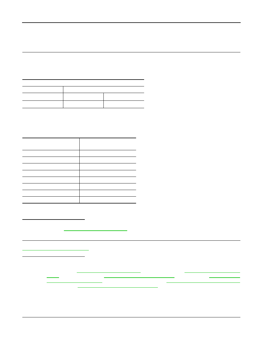
Fuel level sensor unit and fuel pump (fuel level sensor)
Connector
Terminals
B72
*1
2
5
B94
*2
5
6
Resistance (
Ω
)
*
(Approx.)
Fuel gauge indication position
(Approx.)
93
Full
140
3/4
186
1/2
232
1/4
255
1/8
243,5
TURN OFF
255
TURN ON
280.0
Empty