Nissan Qashqai J11. Manual - part 2025


  Index      Nissan     Nissan Qashqai J11 - Service and Repair Manual


Search            


Content   ..  2023  2024  2025  2026   ..


Nissan Qashqai J11. Manual - part 2025


MWI-36

< ECU DIAGNOSIS INFORMATION >

COMBINATION METER

NOTE:
Some items are not available according to vehicle specification.
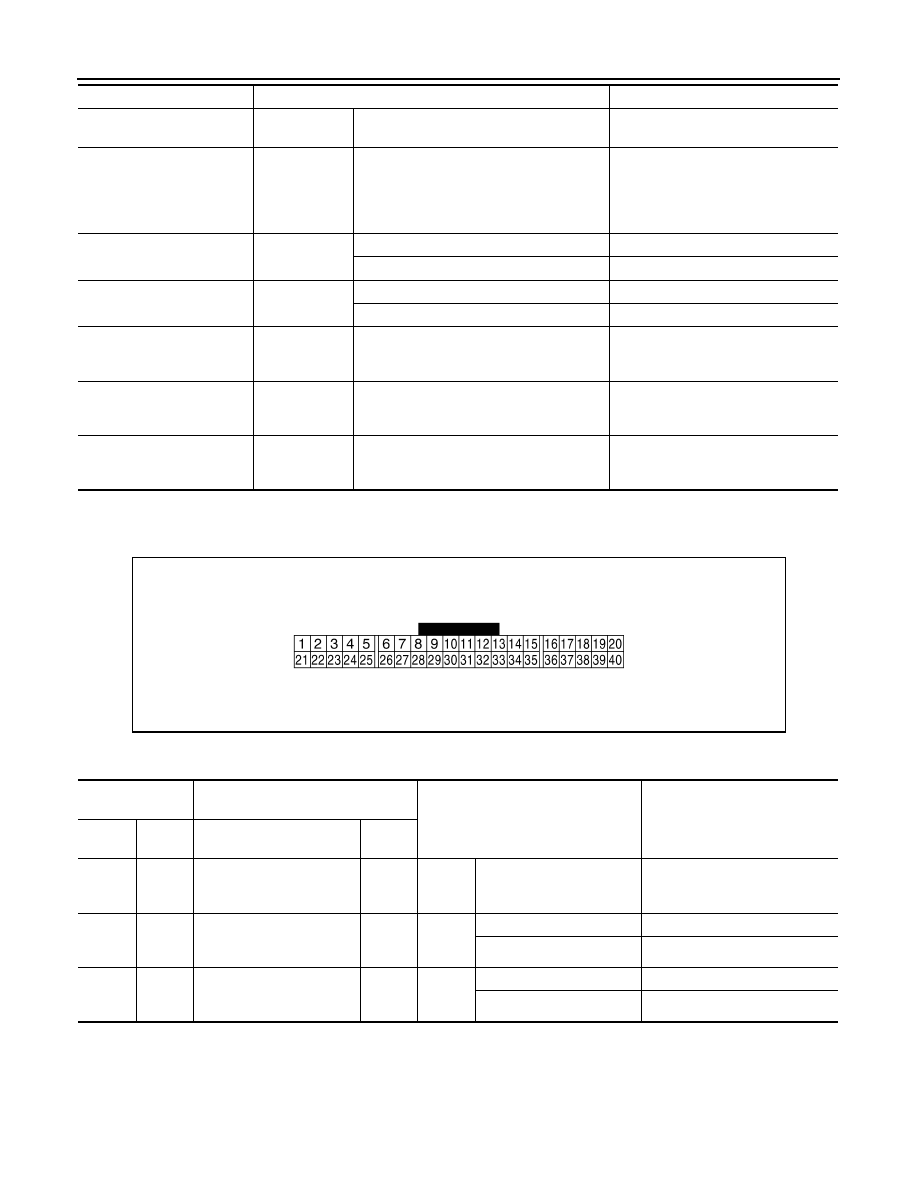
TERMINAL LAYOUT

PHYSICAL VALUES

DISTANCE
[km]

Ignition switch 
ON

Distance to empty calculated by com-
bination meter

OUTSIDE TEMP
[

°

C or 

°

F]

Ignition switch 
ON

Input value of ambient sensor signal 
(CAN communication signal)
NOTE:
This may not match the indicated value 
on the information display.

FUEL LOW SIG

Ignition switch 
ON

Low fuel warning displayed

On

Low fuel warning not displayed

Off

BUZZER

Ignition switch 
ON

Buzzer ON

On

Buzzer OFF

Off

ASCD SPD BLNK

Ignition switch 
ON

NOTE:
This item is displayed, but cannot be moni-
tored.

Off

ASCD STATUS

Ignition switch 
ON

NOTE:
This item is displayed, but cannot be moni-
tored.

Off

ASCD REQ SPD
[km/h or Off]

Ignition switch 
ON

NOTE:
This item is displayed, but cannot be moni-
tored.

Off

Monitor Item

Condition

Value/Status

JSNIA0457ZZ

Terminal No.

(Wire color)

Description

Condition

Value

(Approx.)

+

Signal name

Input/

Output

1

(B)

Ground

Ground 1

Ignition 
switch 
ON

0  V

7

(L)

Ground

Security signal

Input

Ignition 
switch 
OFF

Security warning lamp ON

0 V

Security warning lamp OFF

12 V

9

(P)

Ground

ECO MODE switch signal

Input

Ignition 
switch 
OFF

ECO MODE switch ON

0 V

ECO MODE switch OFF

12 V

MWI

COMBINATION METER

MWI-37

< ECU DIAGNOSIS INFORMATION >

C

D

E

F

G

H

I

J

K

L

M

B

A

O

P

15

(BG)

Ground

Ambient sensor signal 

Input

Ignition 
switch 
ON

17

(BG)

Ground

Satellite switch ground

Ignition 
switch 
ON

0  V

18

(SB)

Ground

TRIP RESET SWITCH

Input

Ignition 
switch 
OFF

TRIP RESET switch ON

12 V

TRIP RESET switch OFF

0 V

20

(R)

Ground

Ambient sensor ground

Ignition 
switch 
ON

0  V

21

(L)

Ground

Steering switch (trip com-
puter) ground

Input

Ignition 
switch 
ON

0  V

22

(LG)

Ground

Steering switch (trip com-
puter) input A signal

Input

Ignition 
switch 
ON

Press the steering switch

0 V

Other than above

5 V

23

(GR)

Ground

Steering switch  (trip com-
puter) input B signal

Input

Ignition 
switch 
ON

Press the steering switch

0 V

Other than above

5 V

25

(Y)

Ground

Brake fluid level switch sig-
nal

Input

Ignition 
switch 
ON

Brake fluid level is normal

5 V

Brake fluid level is less than 
low level

0 V

27

(W)

Ground

LDW OFF switch signal

Input

Ignition 
switch 
OFF

LDW OFF switch ON

0 V

LDW OFF switch OFF

12 V

28

(W)

Ground

Seat belt buckle switch sig-
nal (driver side)

Input

Ignition 
switch 
ON

When driver seat belt is fas-
tened

12 V

When driver seat belt is not 
fastened

0 V

30

(Y)

Ground

M RANGE 

Input

Ignition 
switch 
ON

Manual mode

0 V

Other than the above

12 V

31

(G)

Ground

Not M RANGE

Input

Ignition 
switch 
ON

Manual mode

12 V

Other than the above

0 V

32

(R)

Ground

A/T shift up signal

Input

Ignition 
switch 
ON

Selector lever (+) position

0 V

Other than the above

12 V

33

(W)

Ground

A/T shift down signal

Input

Ignition 
switch 
ON

Selector lever (–) position

0 V

Other than the above

12 V

36

(BR)

Ground

Illumination control switch 
signal (+)

Input

Ignition 
switch 
OFF or 
ON

When illumination switch 
(+) is pressed

0 V

Other than above

5 V

Terminal No.

(Wire color)

Description

Condition

Value

(Approx.)

+

Signal name

Input/

Output

JSNIA0014GB

MWI-38

< ECU DIAGNOSIS INFORMATION >

COMBINATION METER

37

(V)

Ground

Illumination control switch 
signal (-)

Input

Ignition 
switch 
OFF or 
ON

When illumination switch (-) 
is pressed

0 V

Other than above

5 V

38

(P)

Ground

Vehicle speed signal
(8-pulse)

Output

Ignition 
switch 
ON

Speedometer operated
[When vehicle speed is ap-
prox. 40 km/h (25 MPH)]

NOTE:
The maximum voltage varies de-
pending on the specification 
(destination unit).

41

(L)

CAN-H

42

(P)

CAN-L

43

(R)

Ground

Illumination control signal

Output

Ignition 
switch 
ON

• Lighting switch 1ST posi-

tion

• When meter illumination 

is maximum

• Lighting switch 1ST posi-

tion

• When meter illumination 

is step 11

• Lighting switch 1ST posi-

tion

• When meter illumination 

is minimum

12 V

44

(B)

Ground

Fuel level sensor signal 
ground

Ignition 
switch 
ON

0  V

45

(W)

Ground

Battery power supply

Input

Ignition 
switch 
OFF

Battery voltage

46

(BG)

Ground

Ignition signal

Input

Ignition 
switch 
ON

Battery voltage

47

(SB

M-CAN-H

48

(LG)

M-CAN-L

Terminal No.

(Wire color)

Description

Condition

Value

(Approx.)

+

Signal name

Input/

Output

JSNIA0015GB

JPNIA1687GB

JPNIA1686GB

MWI

COMBINATION METER

MWI-39

< ECU DIAGNOSIS INFORMATION >

C

D

E

F

G

H

I

J

K

L

M

B

A

O

P

Fail-safe

INFOID:0000000010329962

The combination meter activates the fail-safe control if the CAN communication lines between each unit are
malfunctioning. 

49

(V)

50

(P)

Oil level sensor signal

Input

Ignition 
switch 
ON

51

(G)

44

(B)

Fuel level sensor signal

Input

Ignition 
switch 
ON

52

(B)

Ground

Ground 2

Ignition 
switch 
ON

0  V

Terminal No.

(Wire color)

Description

Condition

Value

(Approx.)

+

Signal name

Input/

Output

JSNIA3463ZZ

JSNIA3463ZZ

Function

Specifications

Speedometer

Reset to zero by suspending communication.

Tachometer

Engine coolant temperature gauge

Meter illumination control

When suspending communication, changes to 
nighttime mode.

Buzzer

Turned off by suspending communication.

Information dis-
play

Trip computer

Current fuel consumption

• When reception time of an abnormal signal is 

2 seconds or less, the last received datum is 
used for calculation to indicate the result.

• When reception time of an abnormal signal is 

more than 2 seconds, the last result calculat-
ed during normal condition is indicated.

Average fuel consumption

Average vehicle speed

Range (Distance to empty)

Driving distance

An indicated value is maintained at communica-
tions blackout.

Interrupt indication

Door open warning

The indicator turns OFF by suspending commu-
nication.

Low tire pressure warning

Fuel filler cap warning

Odo/trip meter

An indicated value is maintained at communica-
tions blackout.

Shift position indicator

The indicator turns OFF by suspending commu-
nication.


Content   ..  2023  2024  2025  2026   ..