Nissan Qashqai J11. Manual - part 60
FLYWHEEL
EM-179
< UNIT DISASSEMBLY AND ASSEMBLY >
[MR20DD]
C
D
E
F
G
H
I
J
K
L
M
A
EM
N
P
O
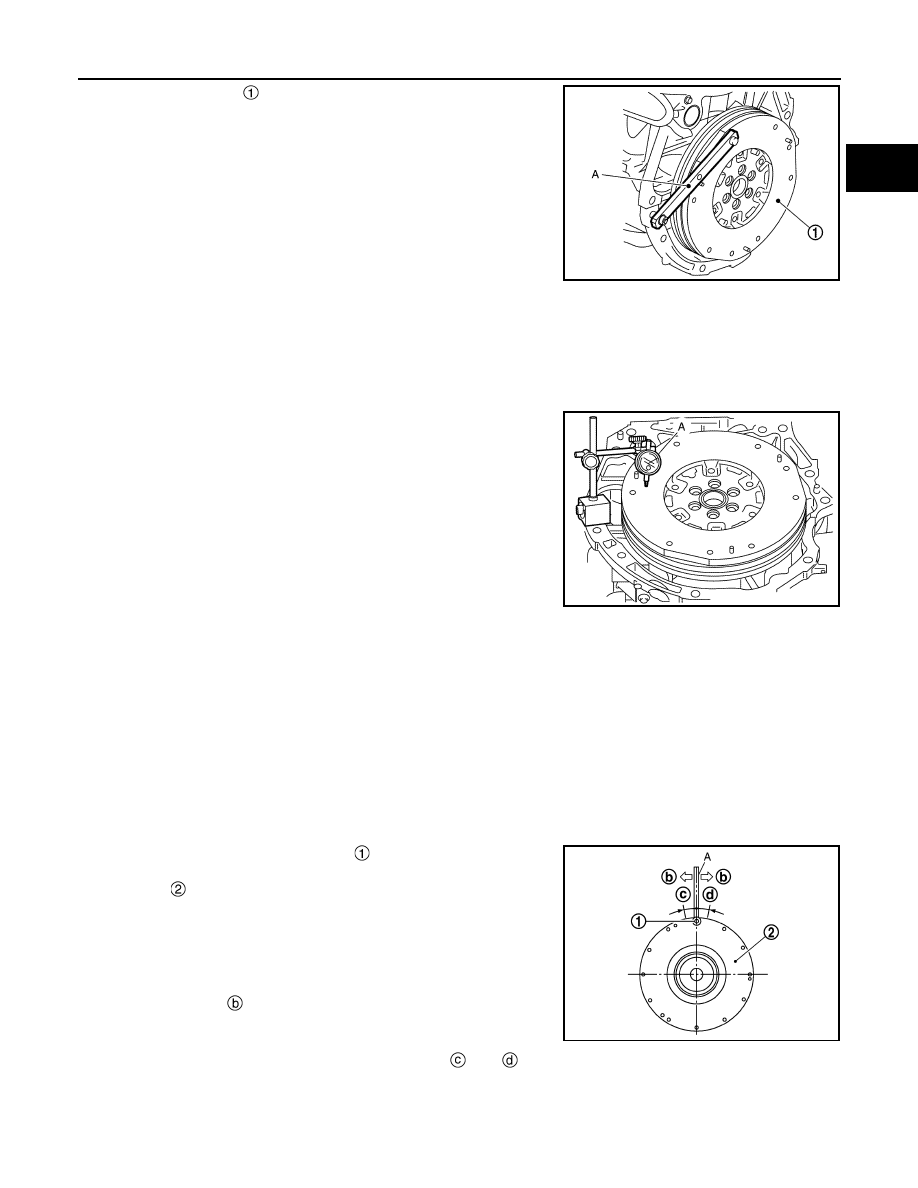
• Secure flywheel
with a stopper plate [SST: KV11105210]
(A), and tighten mounting bolts.
• Using TORX socket (size E20), tighten mounting bolts.
CAUTION:
Never damage or scratch and contact surface for clutch disc of flywheel.
Inspection
INFOID:0000000010715495
FLYWHEEL DEFLECTION
• Measure the deflection of flywheel contact surface to torque with a
dial indicator (A).
• Measure the deflection at 210 mm (8.27 in) diameter.
• If measured value is out of the standard, replace flywheel.
• If a trace of burn or discoloration is found on the surface, repair it
with sandpaper.
MOVEMENT AMOUNT OF FLYWHEEL
CAUTION:
Never disassemble double mass flywheel.
Movement Amount of Thrust (Fore-and-Aft) Direction
• Measure the movement amount of thrust (fore-and-aft) direction when 100 N (10.2 kg, 22 lb) force is added
at the portion of 125 mm (4.92 in) radius from the center of flywheel.
• If measured value is out of the standard, replace flywheel.
Movement Amount in Radial (Rotation) Direction
Check the movement amount of radial (rotation) direction with the following procedure:
1.
Install clutch cover mounting bolt
to clutch cover mounting
hole, and place a torque wrench (A) on the extended line of the
flywheel
center
line.
• Tighten bolt at a force of 9.8 N·m (1.0 kg-m, 87 in-lb) to keep it
from loosening.
2.
Put a mating mark on circumferences of the two flywheel
masses without applying any load (Measurement standard
points).
3.
Apply a force of
[9.8 N·m (1.0 kg-m, 87 in-lb)] in each direc-
tion, and mark the movement amount on the mass on the tran-
saxle side.
4.
Measure the dimensions of movement amounts
and
on circumference of the flywheel on the tran-
saxle side.
JSBIA1438ZZ
Limit : 0.45 mm (0.0177 in) or less.
JSBIA1439ZZ
Standard
: 1.8 mm (0.071 in) or less
Limit
: 33.2 mm (1.307 in) or less.
JPBIA6915ZZ