Nissan Juke F15. Manual - part 985


  Index      Nissan     Nissan Juke F15 (2015 year) - Service and Repair Manual


Search            


Content   ..  983  984  985  986   ..


Nissan Juke F15. Manual - part 985


MA-32

< PERIODIC MAINTENANCE >

ENGINE MAINTENANCE (MR EXCEPT FOR NISMO RS MODELS)

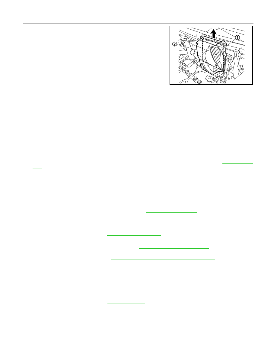
3. Remove the air cleaner filter (1) and air cleaner body (2) from

the air cleaner case.

4. Remove the air cleaner filter from the air cleaner body.

INSTALLATION

Note the following, and install in the reverse order of removal.

• Fixing clips shall be fixed after inserting air cleaner body protrusion to air cleaner case notch hole.

• Make sure that whether air cleaner body has been firmly installed by shaking it.

ENGINE OIL
ENGINE OIL : Draining

INFOID:0000000012200207

WARNING:

• Be careful not to get burned, as engine oil may be hot.

• Prolonged and repeated contact with used engine oil may cause skin cancer. Try to avoid direct skin

contact with used engine oil. If skin contact is made, wash thoroughly with soap or hand cleaner as

soon as possible. 

1. Warm up the engine, and check for engine oil leakage from engine components. Refer to 

LU-9, "Inspec-

tion"

.

2. Stop the engine and wait for 10 minutes.
3. Loosen oil filler cap.
4. Remove drain plug and then drain engine oil.

ENGINE OIL : Refilling

INFOID:0000000012200208

1. Install drain plug with new drain plug washer. Refer to 

EM-46, "Exploded View"

.

CAUTION:

Be sure to clean drain plug and install with new drain plug washer.

2. Refill with new engine oil.

Engine oil specification and viscosity: Refer to 

MA-11, "Fluids and Lubricants"

.

CAUTION:

• The refill capacity depends on the engine oil temperature and drain time. Use these specifica-

tions for reference only.

• Always use oil level gauge to determine the proper amount of engine oil in the engine.

3. Warm up engine and check area around drain plug and oil filter for engine oil leakage.
4. Stop engine and wait for 10 minutes.
5. Check the engine oil level. Refer to 

LU-9, "Inspection"

.

OIL FILTER
OIL FILTER : Removal and Installation

INFOID:0000000012200209

REMOVAL

JPBIA4353ZZ

Tightening torque

: Refer to 

EM-46, "Exploded View"

.

Engine oil capacity

Refer to 

LU-19, "Periodical Maintenance Specification"

.

ENGINE MAINTENANCE (MR EXCEPT FOR NISMO RS MODELS)

MA-33

< PERIODIC MAINTENANCE >

C

D

E

F

G

H

I

J

K

L

M

B

MA

N

O

A

1. Remove oil filter using an oil filter wrench [SST: KV10115801]

(A).

CAUTION:

• Never get burned when engine or engine oil is heated.

• Use a shop cloth to absorb engine oil leakage when

removing.

• Never spill engine oil on the drive belt.

• Completely wipe away any engine oil spilled on the

engine and vehicle.

INSTALLATION

1. Eliminate foreign materials on the oil filter mounting surface.
2. Apply engine oil to the full circumference of the oil seal on a new

oil filter.

3. Screw in oil filter by hand until it contacts mounting surface on

the engine, and then screw in another 2/3 of a turn (A).

NOTE:

Tightening torque is 17.7 N·m (1.8 kg-m).

OIL FILTER : Inspection

INFOID:0000000012200210

INSPECTION AFTER INSTALLATION

1. Use the oil level gauge and check that the oil level is within the standard. Refer to 

LU-28, "Inspection"

.

2. Start the engine. Check for fuel leakage.
3. Stop the engine. After stopping it, leave it for 10 minutes or more.
4. Check the engine oil level again. Fill with engine oil to adjust oil level if necessary. Refer to 

LU-28,

"Inspection"

.

SPARK PLUG
SPARK PLUG : Removal and Installation

INFOID:0000000012200211

REMOVAL

1. Remove the engine cover. Refer to 

EM-191, "Exploded View"

.

2. Remove air inlet tube 2. Refer to 

EM-194, "Removal and Installation"

.

3. Remove the ignition coil. Refer to 

EM-214, "Exploded View"

.

: Vehicle front

JPBIA4450ZZ

SMA010

JPBIA0077ZZ

MA-34

< PERIODIC MAINTENANCE >

ENGINE MAINTENANCE (MR EXCEPT FOR NISMO RS MODELS)

4. Remove spark plug with a spark plug wrench (commercial ser-

vice tool).

CAUTION:

Never drop or shock spark plug.

INSTALLATION

Install in the reverse order of removal.

SPARK PLUG : Inspection

INFOID:0000000012200212

INSPECTION AFTER REMOVAL

Use the standard type spark plug for normal condition.

CAUTION:

• Never drop or shock spark plug.

• Never use a wire brush for cleaning.

• If plug tip is covered with carbon, spark plug cleaner may be

used.

• Spark plug gap adjustment is not required between replace-

ment intervals.

• Measure spark plug gap. when it exceeds the limit, replace

spark plug even if it is with in the specified replacement mile-

age. Refer to 

EM-312, "Spark Plug"

.

EVAP VAPOR LINES
EVAP VAPOR LINES : Inspection

INFOID:0000000012200213

1. Visually inspect EVAP vapor lines for improper attachment and for cracks, damage, loose connections,

chafing and deterioration. Refer to 

EC-1252, "Inspection"

.

2. Inspect fuel tank filler cap vacuum relief valve for clogging, sticking, etc.

Refer to 

EC-1017, "Component Inspection"

.

a

: 14 mm (0.55 in)

JPBIA0030ZZ

Spark plug (Standard type)

: Refer to 

EM-312, "Spark Plug"

.

Cleaner air pressure : Less than 588 kPa (6 kg/cm

2

85 psi)

Cleaning time

: Less than 20 seconds

SMA773C

JPBIA0031ZZ

CHASSIS MAINTENANCE

MA-35

< PERIODIC MAINTENANCE >

C

D

E

F

G

H

I

J

K

L

M

B

MA

N

O

A

CHASSIS MAINTENANCE

EXHAUST SYSTEM
EXHAUST SYSTEM : Inspection

INFOID:0000000012200214

Check exhaust pipes, muffler, and mounting for improper attach-

ment, leakage, cracks, damage or deterioration.

• If anything is found, repair or replace damaged parts.

CVT FLUID (RE0F10B)
CVT FLUID (RE0F10B) : Inspection

INFOID:0000000012200215

CHECKING CVT FLUID

The fluid level should be checked with the fluid warmed up to 50 to 80

°C (122 to 176°F). The fluid level check

procedure is as follows:
1. Check for fluid leakage.
2. With the engine warmed up, drive the vehicle in an urban area.

When ambient temperature is 20

°C (68°F), it takes about 10

minutes for the CVT fluid to warm up to 50 to 80

°C (122 to

176

°F).

3. Park the vehicle on a level surface.
4. Apply parking brake firmly.
5. With engine at idle, while depressing brake pedal, move shift

selector throughout the entire shift range.

6. Pull out the CVT fluid level gauge from the CVT fluid charging

pipe after pressing the tab on the CVT fluid level gauge to

release the lock.

7. Wipe fluid off the CVT fluid level gauge. Insert the CVT fluid

level gauge rotating 180

° from the originally installed position,

then securely push the CVT fluid level gauge until it meets the

top end of the CVT fluid charging pipe.

CAUTION:

When wiping away the CVT fluid level gauge, always use

lint-free paper, not a cloth rag.

SMA211A

SMA146B

SCIA1933E

SCIA1931E


Content   ..  983  984  985  986   ..