Content .. 1368 1369 1370 1371 ..
Nissan Juke F15. Manual - part 1370
C1704, C1705, C1706, C1707 LOW TIRE PRESSURE
WT-23
< DTC/CIRCUIT DIAGNOSIS >
C
D
F
G
H
I
J
K
L
M
A
B
WT
N
O
P
Is the inspection result normal?
YES
>> After erasing DTC record, INSPECTION END.
NO
>> Repair or replace error-detected parts.
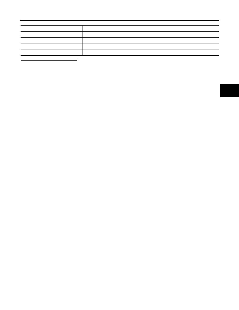
Monitor item
Displayed value
AIR PRESS FL
Approximately equal to the indication on tire gauge value for front LH tire
AIR PRESS FR
Approximately equal to the indication on tire gauge value for front RH tire
AIR PRESS RR
Approximately equal to the indication on tire gauge value for rear RH tire
AIR PRESS RL
Approximately equal to the indication on tire gauge value for rear LH tire