содержание .. 519 520 521 522 ..
Nissan Tiida C11. Manual - part 521
EC-734
< FUNCTION DIAGNOSIS >
[MR18DE]
AUTOMATIC SPEED CONTROL DEVICE (ASCD)
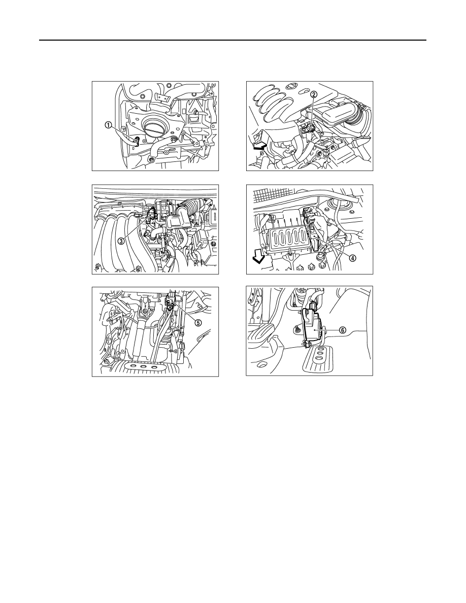
1.
Crankshaft position sensor (POS)
2.
Comshaft position sensor (PHASE)
3.
EVAP canistor purge volume control
solenoid valve
4.
ECM
5.
Stop lamp switch
6.
Accelerator pedal position sensor
PBIA9902J