LG956 Wheel Loader. Manual - part 30
Operation & Maintenance Manual──LG956L Wheel Loader
119
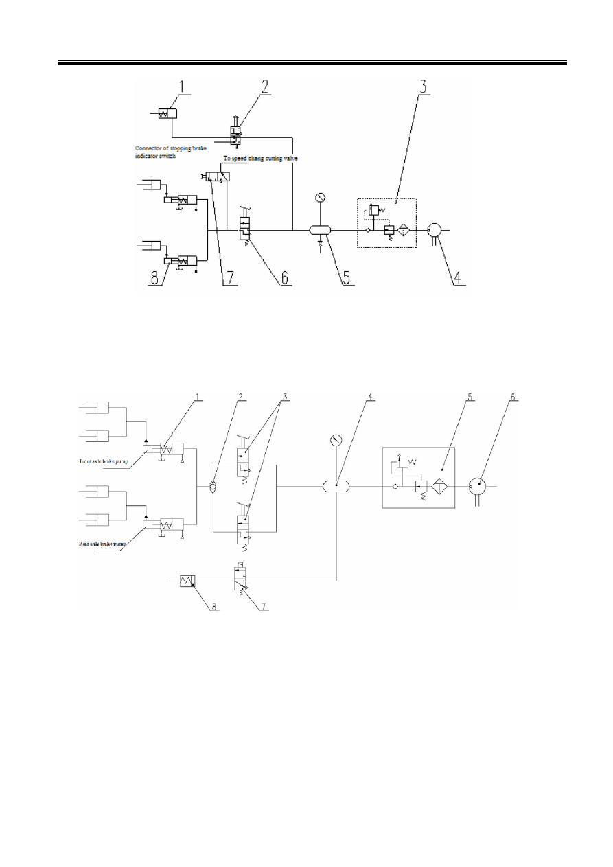
1-Parking Brake Air Chamber 2-Manual Control Brake Valve
3-Combination Valve of Oil Water Separator 4-Air Compressor 5-Air Storage Tank
6- Air Brake Valve 7-Switch Valve 8-Air Booster Pump
Figure 5-4 Single Brake Pedal Braking System Principle Diagram (with power cutting off switch)
1-Air Booster Pump 2-Shuttle Valve 3- Air Brake Valve 4-Air Storage Tank
5-Combination Valve of Oil Water Separator
6-Air Compressor
7-Brake Magnetic Valve
8-Parking Brake Air Chamber
Figure 5-5 Double Brake Pedals Braking Principle Diagram
3.1 Driving Brake System (Single Brake Pedal)
As shown in Figure 5-4, this system is the single line, air pushing oil four wheels caliper disk brake
system using four brake calipers for front and back to increase the safety of whole vehicle..
When the brake pedal is stepped on during driving, the compressed air in air tank 5 flows through air