Mitsubishi Outlander XL. Manual - part 77
HOW TO READ CIRCUIT DIAGRAMS
CIRCUIT DIAGRAMS
90-5
Item
No.
Connector/Grounding
Symbol
Contents
Connector
and terminal
marking
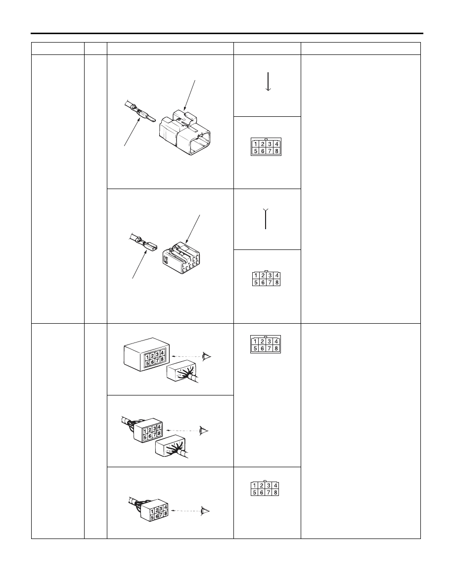
1
The male and female terminals
are indicated as shown. The
connector with male terminal(s)
is called as male connector and
indicated by two connector
contour lines, while the
connector with female
terminal(s) is called as female
connector and indicated by
single connector contour line.
Connector
symbol
marking
2
The symbol indicates the
connector is viewed as shown.
At a device connection, the
connector symbol on the device
side is shown. For an
intermediate connector, the
male connector symbol is
shown. For spare connectors
and check connectors, no
device is connected, and so the
harness-side connector symbol
is shown for these connectors.
However, a data link connector
is exceptional.
ZC5016000000
Male terminal
Male connector
ZC5016110000
Male terminal
ZC5016120000
Male connector
ZC5016010000
Female terminal
Female connector
ZC5016130000
Female terminal
ZC5016140000
Female connector
ZC5016020000
Device
ZC501612AA00
ZC5016030000
Intermediate connector
ZC5016040000
Spare connector, check connector
ZC501614AA00