Mitsubishi Outlander (2003+). Manual - part 540
ON-VEHICLE SERVICE
HEATER, AIR CONDITIONER AND VENTILATION
55A-55
NOTE: The low-pressure service valve should be
connected to the suction hose.
8. Start the engine.
9. Operate the air conditioner and set at the lowest
temperature (MAX. COOL).
10.Fix the engine speed at 1,500 r/min.
11.Tighten the handle of the adaptor valve (valve
open), and replenish refrigerant while checking
the quantity through the sight glass.
12.After replenishing is completed, turn the handle of
the adaptor valve all the way back (valve close),
and remove the quick joint.
NOTE: When there is remainder of refrigerant in
the service can, keep it for next use with the
charge value and the valve of the adaptor valve
being closed.
DISCHARGING SYSTEM
M1552013000086
Use the refrigerant recovery unit to discharge
refrigerant gas front the system.
NOTE: Refer to the Refrigerant Recovery and
Recycling Unit instruction Manual for operation of the
unit.
REFILLING OF OIL IN THE A/C SYSTEM
M1552020000055
Too little oil will provide inadequate compressor
lubrication and cause a compressor failure. Too
much oil will increase discharge air temperature.
When a compressor is installed at the factory, it
contains 120 mL <MSC90CA> or 140mL
<MSC105CA> of compressor oil. While the A/C
system is in operation, the oil is carried through the
entire system by the refrigerant. Some of this oil will
be trapped and retained in various parts of the
system.
When the following system components are
changed, it is necessary to add oil to the system to
replace the oil being removed with the component.
Compressor oil: SUN PAG 56
Quantity
Evaporator: 60 mL
Condenser: 15 mL
Flexible suction hose: 10 mL
Receiver: 10 mL
PERFORMANCE TEST
M1552001400333
1. The vehicles to be tested should be in a place that
is not in direct sunlight.
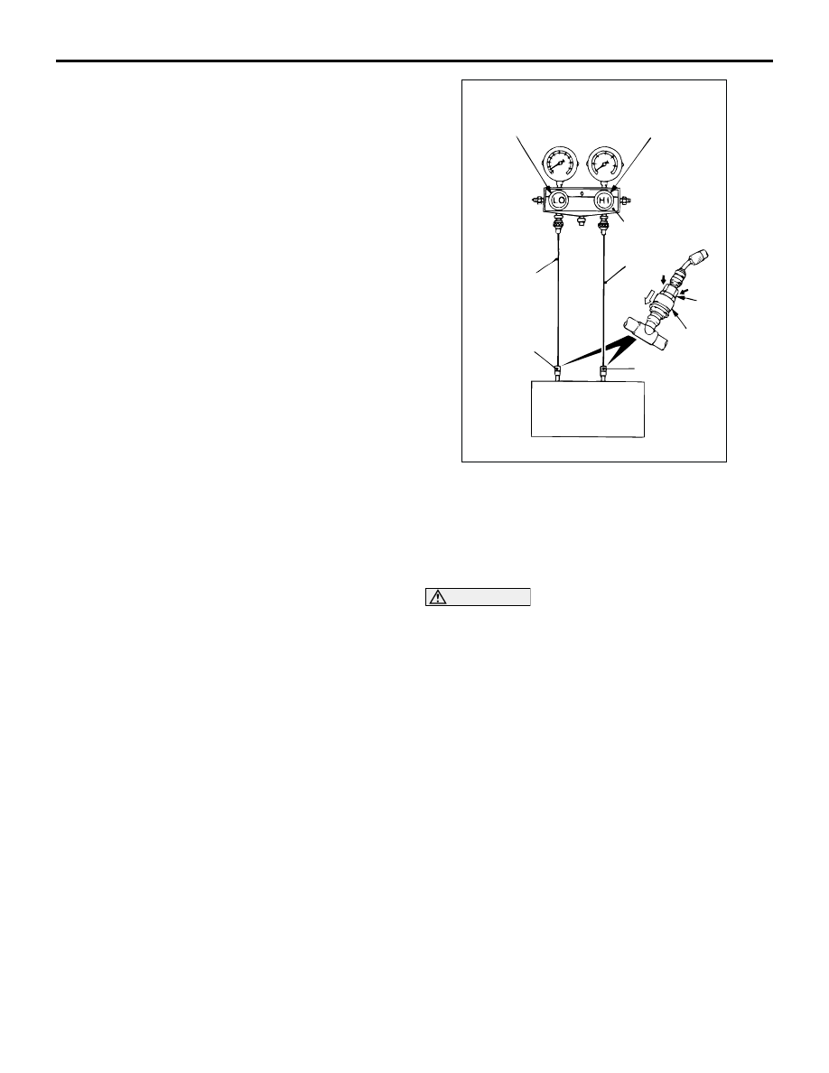
2. Close the high and low-pressure valve of the
gauge manifold.
3. Connect the charging hose (blue) to the
low-pressure valve and connect the charging
hose (red) to the high-pressure valve of the gauge
manifold.
CAUTION
•
To connect the quick joint, press section A
firmly against the service valve until a click is
heard.
•
When connecting, run your hand along the
hose while pressing to ensure that there are
no bends in the hose.
4. Install the quick joint (for low-pressure) to the
charging hose (blue), and connect the quick joint
(for high-pressure) to the charging hose (red).
NOTE: The high-pressure service valve is on the
A/C pipe and the low-pressure service valve is on
the suction hose.
5. Connect the quick joint (for low-pressure) to the
low-pressure service valve and connect the quick
joint (for high-pressure) to the high-pressure
service valve.
6. Start the engine.
7. Set the A/C controls as follows:
•
A/C switch: A/C
−
ON position
•
Mode selection: FACE position
•
Temperature control: MAXIMUM COOLING
position
•
Air selection: RECIRCULATION position
AC001388
Low-pressure
valve
High-pressure
valve
Gauge manifold
Charging
hose (red)
A
Sleeve
Charging
hose (blue)
Adaptor valve
(for low-
pressure)
Low-
pressure
service
valve
High-
pressure
service
valve
AB
Adaptor valve
(for high-
pressure)