Mitsubishi Outlander (2003+). Manual - part 427


  Index      Mitsubishi     Mitsubishi Outlander - service repair manual 2003 year


Search            


Content   ..  425  426  427  428   ..


Mitsubishi Outlander (2003+). Manual - part 427


SPEAKER

CHASSIS ELECTRICAL

54A-103

SPEAKER

REMOVAL AND INSTALLATION

M1544002600517

AC102825 AD

1

2

3

4

6

5

1.5 ± 0.5 N·m

1.5 ± 0.5 N·m

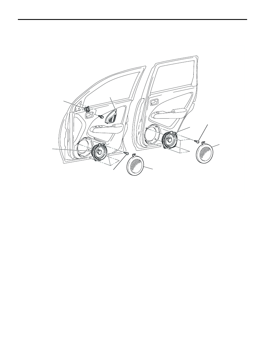
Front door speaker removal 
steps

1.

Front door speaker garnish

2.

Front door speaker

Rear door speaker removal 
steps

3.

Rear door speaker garnish

4.

Rear door speaker
Tweeter removal steps

5.

Delta cover (Refer to GROUP 51, 
Door Mirror 

P.51-57

.)

6.

Tweeter

ANTENNA

CHASSIS ELECTRICAL

54A-104

ANTENNA

ANTENNA

REMOVAL AND INSTALLATION

M1544002900585

Pre-removal and Post-installation Operation

Front pillar trim, Quarter trim upper, Quarter trim lower, 

Center pillar trim lower, Center pillar trim upper (Refer to 

GROUP 52A, Trim 

P.52A-18

.)

Assist Grip, Headlining (Refer to GROUP 52A, Headlining 

P.52A-27

.)

Instrument Panel Removal and Installation (Refer to 

GROUP 52A, Instrument Pane

P.52A-2

<LHD> or 

P.52A-8

<RHD>.)

AC300925 AB

1

3

2

4

3.0 ± 1.0 N·m

Removal steps

1. Rod assembly
2. Antenna nut

3. Base
4. Antenna feeder assembly

Removal steps (Continued)

REAR WINDOW DEFOGGER

CHASSIS ELECTRICAL

54A-105

REAR WINDOW DEFOGGER

GENERAL INFORMATION

M1543000100397

Rear Defogger operation
The defogger relay turns ON if the defogger switch 
built-in the A/C-ECU is turned ON when the ignition 
switch is in the "ON" position. When the defogger 
relay turns ON, power is supplied to the defogger 
and the defogger is activated. The defogger comes 
with a timer function that causes the defogger switch 
to automatically turn OFF in about 11 minutes 
(manual A/C) or about 20 minutes (automatic A/C) 
after the defogger switch is turned ON.

TROUBLESHOOTING

M1543000701110

The rear window defogger is controlled by the 
A/C-ECU. For troubleshooting, refer to GROUP 55A, 
Troubleshooting 

P.55A-4

 or GROUP 55B, 

Troubleshooting 

P.55B-28

.

ON-VEHICLE SERVICE

PRINTED HEATER LINES CHECK

M1543001800355

1. Run engine at 2,000 r/min. Check heater element 

with battery at full.

2. Turn "ON" rear window defogger switch. Measure 

heater element voltage with circuit tester at rear 
window glass centre A. Condition is good if it 
indicates about six volts.

3. If 12 volts is indicated at A, there is a break in the 

negative terminals from A. Move test bar slowly to 
negative terminal to detect where voltage 
changes suddenly (0volts).

4. If 0 volts is indicated at A, there is a break in the 

positive terminals from A. Defect where the 
voltage changes suddenly (12 volts) in the same 
method described above.

REAR WINDOW DEFOGGER SWITCH

REMOVAL AND INSTALLATION

M1543006200347

Refer to GROUP 55A, Heater Control Assembly and 
Blower Switch Assembly 

P.55A-60

.

INSPECTION

M1543019502656

DEFOGGER RELAY CHECK

ACX00813

Normal characterstic curve

Abnormal characterstic curve

A (Center point)

Approximately 6 V

Negative 
terminal

Print heater line

Positive 
terminal

Open circuit point

Voltage

AC

Voltage

Negative 
terminal

Print heater line

Positive 
terminal

Battery voltage

Tester 
connection

Specified 
condition

Not supplied

 5

Open circuit

Connect terminal 
1 to the positive 
battery terminal

Connect terminal 
3 to the negative 
battery terminal

 5

Less than 2 
ohms

AC212486

OFF

ON

3

4

5

1

Defogger relay

Junction block

AB

NOTES


Content   ..  425  426  427  428   ..