Mitsubishi Outlander (2003+). Manual - part 232
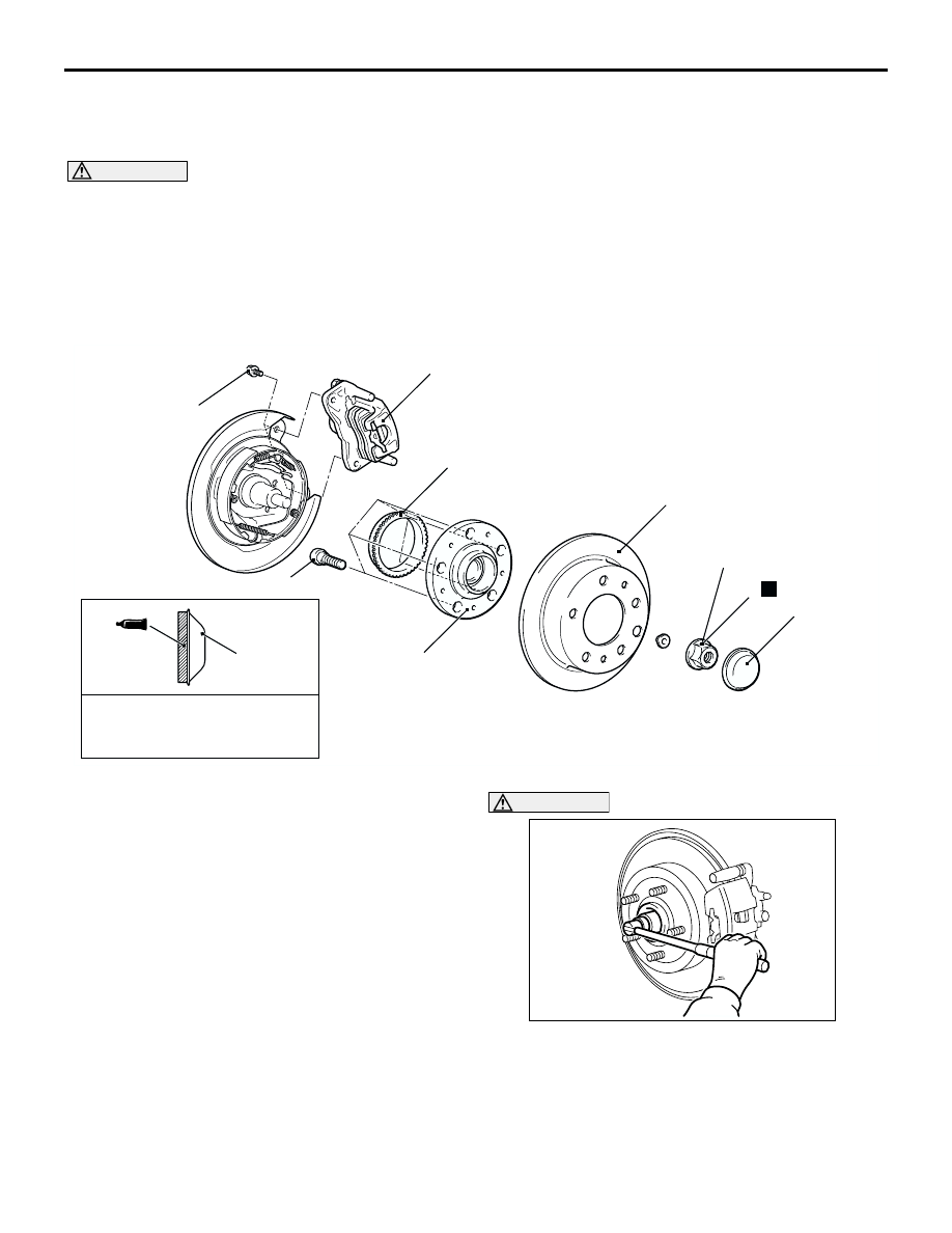
REAR AXLE HUB ASSEMBLY
REAR AXLE <2WD>
27A-5
REAR AXLE HUB ASSEMBLY
REMOVAL AND INSTALLATION
M1271002000347
CAUTION
•
Care must be taken not to scratch or damage the teeth of the ABS rotor. The ABS rotor must never
be dropped. If the teeth of the ABS rotor are chipped, resulting in a deformation of the ABS rotor,
it will not be able to accurately detect the wheel rotation speed, and the system will not function
normally.
•
The rear hub assembly should not be dismantled. When removing the rear hub assembly, the
wheel bearing inner race may be left at the spindle side. In this case, always replace the rear hub
assembly, otherwise the hub will damage the oil seal, causing oil leaks or excessive play.
REMOVAL SERVICE POINTS
<<A>> CALIPER ASSEMBLY REMOVAL
Secure the removed caliper assembly with wire, etc.
<<B>> SELF-LOCKING NUT REMOVAL
CAUTION
Do not apply the vehicle weight to the wheel
bearing while loosening the self-locking nut, or
the wheel bearing will be damaged.
AC301185
Semi-drying sealant:
3M ATD Part No. 8663 or
equivalent
2
3
4
5
6
7
N
175 ± 25 N·m
3
AB
1
60 ± 5 N·m
Removal steps
<<A>>
1.
Caliper assembly
2.
Brake disc
3.
Hub cap
<<B>> >>B<<
4.
Self-locking nut
5.
Rear hub assembly
<<C>> >>A<<
6.
ABS rotor
7.
Hub bolt
AC301112
AB