Mitsubishi Montero (2004+). Manual - part 559


  Index      Mitsubishi     Mitsubishi Montero - service repair manual 2004 year


Search            


Content   ..  557  558  559  560   ..


Mitsubishi Montero (2004+). Manual - part 559


VIDEO ENTERTAINMENT SYSTEM (VES)

TSB Revision

CHASSIS ELECTRICAL

54A-205

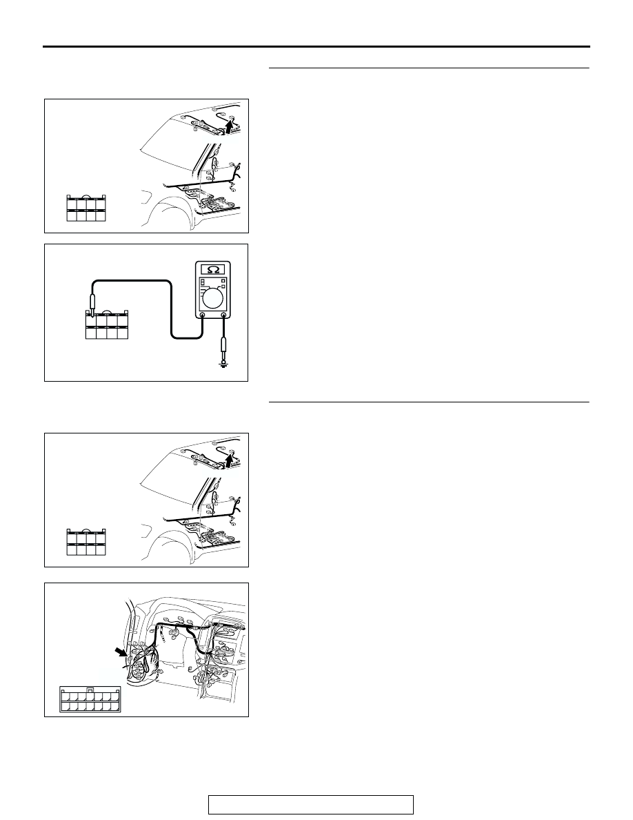
STEP 11. Measure the resistance at rear display connector 
F-33 in order to the ground circuit to the rear display.
(1) Disconnect rear display connector F-33, and measure at 

the wiring harness side.

(2) Measure the resistance value between terminal 24 and 

ground.

• The resistance should be 2 ohm or less.

Q: Is the measured resistance 2 ohms or less?

YES : Go to Step 13.
NO :  Go to Step 12.

STEP 12. Check the wiring harness between rear display 
connector F-33 (terminal 24) and ground.

NOTE: Also check intermediate connector D-34 for loose, cor-
roded, or damaged terminals, or terminals pushed back in the 
connector. If intermediate connector D-34 is damaged, repair or 
replace. Refer to GROUP 00E, Harness Connector Inspection 

P.00E-2

.

Q: Is the wiring harness between rear display connector 

F-33 (terminal 24) and ground in good condition?
YES : 
Go to Step 13.
NO :  Repair the wiring harness. The rear display works 

normally.

AC309223

AB

CONNECTOR: F-33

HARNESS SIDE

F-33 (B)

21

22

23

24

25

26

27

28

AC209364

21

22

23

24

25

26

27

28

CONNECTOR F-33 
(HARNESS SIDE)

KO

AC309223

AB

CONNECTOR: F-33

HARNESS SIDE

F-33 (B)

21

22

23

24

25

26

27

28

AC309207

AD

CONNECTOR: D-34

HARNESS SIDE

4

11

1

8 9

2

10

3

5

1213

6

14

7

VIDEO ENTERTAINMENT SYSTEM (VES)

TSB Revision

CHASSIS ELECTRICAL

54A-206

STEP 13. Check the video controller unit connector F-34 
for loose, corroded or damaged terminals, or terminals 
pushed back in the connector.

Q: Is the video controller unit connector F-34 in good 

condition?
YES : 
Go to Step 14.
NO :  Repair or replace the component(s). Refer to GROUP 

00E, Harness Connector Inspection 

P.00E-2

. The 

rear display works normally.

STEP 14. Measure at video controller unit connector F-34 
in order to power supply circuit to video controller unit 
(ACC).

(1) Disconnect video controller unit connector F-34, and 

measure at the wiring harness side.

(2) Turn the ignition switch to "ACC" position.

(3) Measure the voltage between terminal 10 and ground.

• The voltage should measure approximately 12 volts 

(battery positive voltage).

Q: Is the measured voltage approximately 12 volts (battery 

positive voltage)?
YES : 
Go to Step 16.
NO :  Go to step 15.

AC309223

AC

CONNECTOR: F-34

HARNESS SIDE

AC309223

AC

CONNECTOR: F-34

HARNESS SIDE

AC209365

CONNECTOR F-34 
(HARNESS SIDE)

JD

VIDEO ENTERTAINMENT SYSTEM (VES)

TSB Revision

CHASSIS ELECTRICAL

54A-207

STEP 15. Check the wiring harness between video 
controller unit connector F-34 (terminal 10) and ignition 
switch (ACC).

AC309223

AC

CONNECTOR: F-34

HARNESS SIDE

VIDEO ENTERTAINMENT SYSTEM (VES)

TSB Revision

CHASSIS ELECTRICAL

54A-208

NOTE: Also check joint connector (7) D-02, intermediate con-
nector D-28 and D-139 and junction block D-208 and D-221 for 
loose, corroded, or damaged terminals, or terminals pushed 
back in the connector. If joint connector (7) D-02 or intermedi-
ate connector D-28 and D-139 or junction block D-208 and 
D-221 is damaged, repair or replace. Refer to GROUP 00E, 
Harness Connector Inspection 

P.00E-2

.

Q: Is the wiring harness between video controller unit 

connector F-34 (terminal 10) and the ignition switch 
(ACC) in good condition?
YES : 
Go to Step 16.
NO :  Repair the wiring harness. The rear display works 

normally.

AC309208

HARNESS SIDE

D-02

D-28

AD

CONNECTORS: D-02, D-28, D-139

D-02

D-28

D-139

D-139

AC309218

CONNECTORS: D-208, D-221

JUNCTION BLOCK 
(FRONT VIEW)

D-221

D-208

HARNESS SIDE

D-208

D-221

HARNESS SIDE

AB


Content   ..  557  558  559  560   ..