Mitsubishi Montero (2004+). Manual - part 528


  Index      Mitsubishi     Mitsubishi Montero - service repair manual 2004 year


Search            


Content   ..  526  527  528  529   ..


Mitsubishi Montero (2004+). Manual - part 528


HEADLIGHT, FRONT SIDE MARKER LIGHT AND POSITION LIGHT ASSEMBLY

TSB Revision

CHASSIS ELECTRICAL

54A-81

NOTE: When measuring the intensity, maintain an engine 
speed of 2,000 r/min, with the battery fully charged.
There may be special local regulations pertaining to headlight 
intensity. Be sure to make any adjustments necessary to satisfy 
such regulations.
If an illuminometer is used to make the measurements, convert 
its values to photometer values by using the following formula.

I =Er2 Where:

• I = intensity (cd)

• E = illumination (lux)

• r = distance (m) from headlights to illuminometer
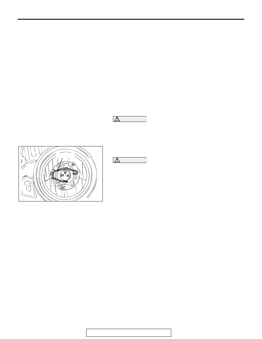
 BULB REPLACEMENT

M1542001300153

1. Disconnect the connector.
2. Remove the sealing cover.

CAUTION

Do not touch the surface of the bulb with hands or dirty 
gloves as the bulb may pop after a short time. If the sur-
face does become dirty, clean it with alcohol or thinner, 
and let it dry thoroughly before installing.
3. Unhook the spring securing the bulb, and then remove the 

bulb.

CAUTION

Do not touch the surface of the bulb with hands or dirty 
gloves as the bulb may pop after a short time. If the sur-
face does become dirty, clean it with alcohol, and let it dry 
thoroughly before installing.
4. Install the spring and sealing cover securely after the bulb 

replacement, or the lens will be out of focus, or water will get 
inside the light unit.

ACX00789AC

SPRING

HEADLIGHT, FRONT SIDE MARKER LIGHT AND POSITION LIGHT ASSEMBLY

TSB Revision

CHASSIS ELECTRICAL

54A-82

HEADLIGHT AND FRONT COMBINATION LIGHT

REMOVAL AND INSTALLATION

M1542002700381

WARNING

Before removal of the air bag module, refer to GROUP 52B, SRS Service Precautions 
(

P.52B-18

) and Air Bag Module and Clock Spring (

P.52B-217

).

When removing and installing the steering wheel, do not let it bump against the air bag 
module.

Post-installation operation
• Headlight aiming adjustment (Refer to 

P.54A-79

).

ACX01803AC

1

2

3

BATTERY

AC204111AB

4.9 ± 0.7 N

·

m

43 ± 6 in-lb

4.9 ± 0.7 N

·

m

43 ± 6 in-lb

4.9 ± 0.7 N

·

m

43 ± 6 in-lb

4

1.

ETACS-ECU

2.

FRONT-ECU

3.

COLUMN SWITCH (REFER TO 

P.54A-120

).

HEADLIGHT REMOVAL STEPS

RADIATOR GRILL (REFER TO 
GROUP 51, FRONT BUMPER 

P.51-3

).

<<A>>

4.

HEADLIGHT ASSEMBLY

HEADLIGHT, FRONT SIDE MARKER LIGHT AND POSITION LIGHT ASSEMBLY

TSB Revision

CHASSIS ELECTRICAL

54A-83

REMOVAL SERVICE POINT

.

<<A>> HEADLIGHT ASSEMBLY REMOVAL
Remove the headlight mounting nut to remove the headlight. 
The nut is found at the inner side of the vehicle among the nuts 
that appear when the splash shield is removed at the front side. 

AC204789AB

5.0 ± 1.0 N

·

m

44 ± 9 in-lb

5

6

DRL-ECU REMOVAL STEPS

5.

DRL-ECU

6.

DRL-ECU BRACKET

ACX00791AB

INSIDE OF 
VEHICLE

FOG LIGHT

TSB Revision

CHASSIS ELECTRICAL

54A-84

FOG LIGHT

FOG LIGHT DIAGNOSIS

M1542010500252

The fog lights are controlled by the Simplified Wiring 
System (SWS). For troubleshooting, refer to GROUP 
54B, SWS Diagnosis 

P.54B-6

.

ON-VEHICLE SERVICE

FOG LIGHT AIMING

M1542001100331

PRE-AIMING INSTRUCTIONS

1. Inspect for badly rusted or faulty headlight assemblies.
2. These conditions must be corrected before a satisfactory 

adjustment can be made.

3. Inspect tire inflation, and adjust if necessary.
4. If the fuel tank is not full, place a weight in luggage room of 

vehicle to simulate weight of a full tank [3 kg (6.5 pounds) 
per gallon.]

5. There should be no other load in the vehicle other than 

driver or substituted weight of approximately 70 kg (150 
pounds) placed in driver's position.

6. Thoroughly clean fog light lenses.
7. Place the vehicle on a level floor, perpendicular to a flat 

screen 7.62 m (25.0 feet) away from the bulb center-marks 
on the fog light lens.

8. Rock vehicle sideways to allow vehicle to assume its normal 

position.

9. Bounce the front suspension through three (3) oscillations 

by applying the body weight to hood or bumper.

10.Measure the center of the fog lights as shown in the 

illustration.

11.Four lines of adhesive tape (or equivalent markings) are 

required on screen or wall:

(1) Position a vertical tape or mark so that it is aligned with 

the vehicle center line.

(2) Measure the distance from the center-marks on the fog 

light lens to the floor. Transfer the measurement to the 
screen. Horizontal tape or mark on the screen is for 
reference of vertical adjustment.

AC204112 AB

CENTER OF 
THE LIGHT

AC005167

SCREEN

(1)

(2)

(3)

(3)

FOG LIGHT CENTER

VEHICLE CENTER  
LINE

7.62m (25.0 ft)

AD


Content   ..  526  527  528  529   ..