Mitsubishi Montero (2004+). Manual - part 276


  Index      Mitsubishi     Mitsubishi Montero - service repair manual 2004 year


Search            


Content   ..  274  275  276  277   ..


Mitsubishi Montero (2004+). Manual - part 276


MULTIPORT FUEL INJECTION (MFI) DIAGNOSIS

TSB Revision

MULTIPORT FUEL INJECTION (MFI)

13A-591

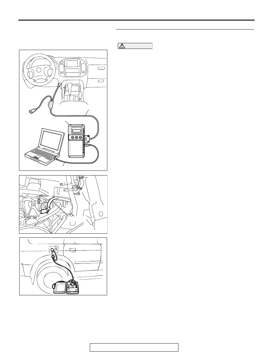
STEP 14. Using scan tool MB991958, check data list item 
73: Fuel Tank Differential Pressure Sensor.

CAUTION

To prevent damage to scan tool MB991958, always turn the 
ignition switch to the "LOCK" (OFF) position before con-
necting or disconnecting scan tool MB991958.
(1) Connect scan tool MB991958 to the data link connector.

(2) Disconnect hose F from the evaporative emission canister 

side, and plug the hose.

(3) Turn the ignition switch to the "ON" position.
(4) Remove the fuel cap.
(5) Set scan tool MB991958 to the data reading mode.

Item 73, Fuel Tank Differential Pressure Sensor.

• The fuel tank pressures reading on the scan tool 

should be 

−1.5 to 1.5 kPa (−0.443 to 0.443 inHg).

(6) Connect an evaporative emission system pressure pump to 

the fuel tank filler tube and pressurize the fuel tank.

• The fuel tank pressure reading should increase.

(7) Disconnect an evaporative emission system pressure pump 

and connect hose F.

(8) Turn the ignition switch to the "LOCK" (OFF) position and 

disconnect scan tool MB991958.

Q: Is the fuel tank pressure between 

1.5 and 1.5 kPa 

(

0.443 and 0.443 inHg)?

YES : It can be assumed that this malfunction is intermittent. 

(Refer to GROUP 00, How to Use 
Troubleshooting/Inspection Service Points 

− How to 

Cope with Intermittent Malfunction 

P.00-6

). Go to 

Step 15.

NO :  Replace the PCM (Refer to 

P.13A-1014

). Go to Step 

15   .

AC306409AF

MB991911

MB991824

MB991827

AC102602 AC

HOSE F

ACX01358

MULTIPORT FUEL INJECTION (MFI) DIAGNOSIS

TSB Revision

MULTIPORT FUEL INJECTION (MFI)

13A-592

STEP 15. Perform the OBD-II drive cycle.
(1) Carry out a test drive with the drive cycle pattern (Refer to 

Diagnostic Function 

− OBD-ll Drive Cycle − Procedure 1 − 

Evaporative Emission System Leak Monitor 

P.13A-4

).

(2) Read the diagnostic trouble code (DTC).
Q: Is DTC P0452 set?

YES : Repeat the troubleshooting from Step 2.
NO :  The procedure is complete.

DTC P0453: Evaporative Emission System Pressure Sensor High Input

AC203991

SYSTEM DIAGRAM

A

B

C

D

E

F

G

H

I

J

K

L

M

N

O

Q

S

R

P

FUEL TANK

CHECK VALVE B

CHECK VALVE A

EVAPORATIVE
EMISSION
PURGE
SOLENOID

EVAPORATIVE EMISSION
VENTILATION SOLENOID

EVAPORATIVE
EMISSION
CANISTER

VENT PIPE
ASSEMBLY

AC

FUEL TANK DIFFERENTIAL
PRESSURE SENSOR

ONBOARD REFUELING
VAPOR RECOVERY(ORVR)
VENT VALVE MODULE

MULTIPORT FUEL INJECTION (MFI) DIAGNOSIS

TSB Revision

MULTIPORT FUEL INJECTION (MFI)

13A-593

FUEL TANK
DIFFERENTIAL
PRESSURE
SENSOR

POWERTRAIN CONTROL
MODULE (PCM)

AC309251

Fuel Tank Differential Pressure Sensor Circuit

AB

FUEL TANK
DIFFERENTIAL
PRESSURE
SENSOR

POWERTRAIN CONTROL
MODULE (PCM)

AC309251

MULTIPORT FUEL INJECTION (MFI) DIAGNOSIS

TSB Revision

MULTIPORT FUEL INJECTION (MFI)

13A-594

.

CIRCUIT OPERATION

• The PCM (terminal 97) supplies a 5-volt refer-

ence signal to the fuel tank differential pressure 
sensor (terminal 3). The fuel tank differential 
pressure sensor (terminal 2) is grounded through 
the PCM (terminal 96).

• The fuel tank differential pressure sensor (termi-

nal 1) returns a voltage signal to the PCM (termi-
nal 82) that is proportional to the pressure in the 
fuel tank.

.

TECHNICAL DESCRIPTION

• The PCM monitors the fuel tank differential pres-

sure sensor output voltage.

• The PCM determines whether the fuel tank differ-

ential pressure sensor signal voltage is within 
normal operating parameters.

.

DESCRIPTIONS OF MONITOR METHODS

• Compare purge solenoid status with fuel tank dif-

ferential pressure sensor output voltage.

.

MONITOR EXECUTION

• Continuous.

.

MONITOR EXECUTION CONDITIONS (Other 
Monitor and Sensor)

Other Monitor (There is no temporary DTC stored 

in memory for the item monitored below)

• Evaporative emission purge solenoid monitor

• Evaporative emission ventilation solenoid monitor

 Sensor (The sensors below are determined to be 

normal)

• Volume airflow sensor

• Barometric pressure sensor

• Intake air temperature sensor

• Engine coolant temperature sensor

AC203998

CONNECTOR: D-112

AB

D-112

AC203993

CONNECTORS: D-134, D-135

AB

D-134
(GR)

D-135
(GR)

PCM

AC203999

CONNECTORS: E-111, E-113

AB

E-113

E-111

AC204000

CONNECTOR: F-07

AB

F-07 (B)

ACX00218

CONNECTOR : G-05

AQ

G-05 (B)

SECOND SEAT UNDER
SERVICE HOLE


Content   ..  274  275  276  277   ..