Mitsubishi Montero (2004+). Manual - part 256


  Index      Mitsubishi     Mitsubishi Montero - service repair manual 2004 year


Search            


Content   ..  254  255  256  257   ..


Mitsubishi Montero (2004+). Manual - part 256


MULTIPORT FUEL INJECTION (MFI) DIAGNOSIS

TSB Revision

MULTIPORT FUEL INJECTION (MFI)

13A-511

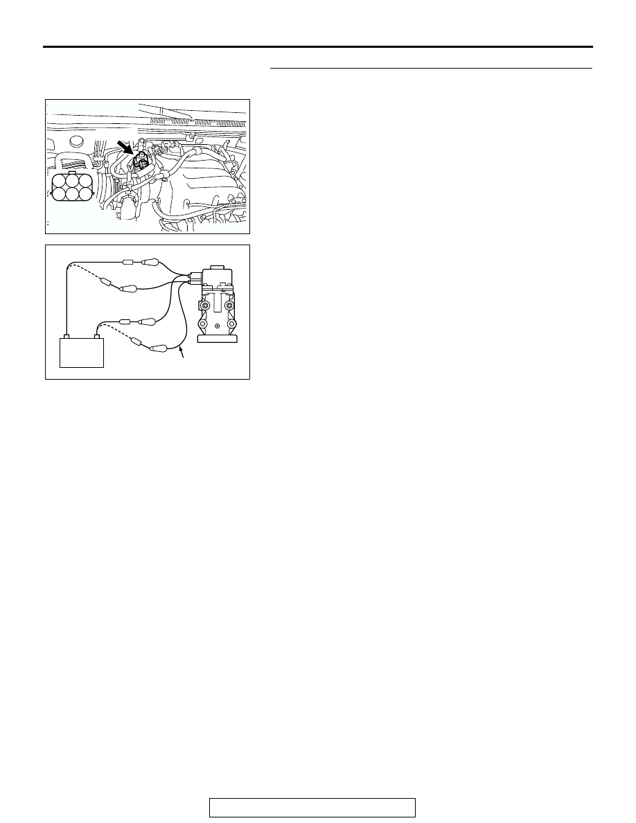
STEP 9. Check the EGR valve operation using special tool 
MB991658.
(1) Remove the EGR valve.

(2) Connect special tool MB991658 to the EGR valve. (All 

terminals should be connected.)

(3) Use the jumper wires to connect terminal No. 2 of the EGR 

valve connector to the positive battery terminal.

(4) Check to ensure that the motor operates when the terminal 

No. 1 and No. 3 of the EGR valve connector are 
respectively connected to the negative battery terminal 
using a jumper wire.

• Vibration should be present at each application of volt-

age to test clip combination.

(5) Then. Use jumper wires to connect the terminal No. 5 of the 

EGR valve connector to the positive battery terminal.

(6) Check to ensure that the motor operates when the terminal 

No. 4 and No. 6 of the EGR valve connector are 
respectively connected to the negative battery terminal 
using a jumper wire.

• Vibration should be present at each application of volt-

age to test clip combination.

(7) Reinstall the EGR valve, using a new gasket, and tighten to 

the specified torque.

Tighten torque : 24 

± 3 Nm [17 ± 3 ftIb]

Q: Is the EGR valve operating properly?

YES : Go to Step 10.
NO :  Replace the EGR valve. Then go to Step 12.

AK200967

1

2

3

4

5

6

AB

HARNESS 
CONNECTOR: 
COMPONENT SIDE

B-56(GR)

CONNECTOR: B-56

AK000888

BATTERY

MB991658

AC

MULTIPORT FUEL INJECTION (MFI) DIAGNOSIS

TSB Revision

MULTIPORT FUEL INJECTION (MFI)

13A-512

STEP 10. Check for harness damage between MFI relay 
connector B-22X (terminal No. 1) and EGR valve connector 
B-56 (terminal No. 2, No. 5).
Q: Is the harness wire in good condition?

YES : Go to Step 11.
NO :  Repair it. Then go to Step 12.

AK200951

2 1

3

4

B-22X

AB

CONNECTOR: B-22X

HARNESS 
CONNECTOR: 
COMPONENT SIDE

AK200967

1

2

3

4

5

6

AB

HARNESS 
CONNECTOR: 
COMPONENT SIDE

B-56(GR)

CONNECTOR: B-56

MULTIPORT FUEL INJECTION (MFI) DIAGNOSIS

TSB Revision

MULTIPORT FUEL INJECTION (MFI)

13A-513

STEP 11. Check for harness damage between EGR valve 
connector B-56 and PCM connector D-132.

a. EGR valve connector B-56 (terminal No. 1) and PCM con-

nector D-132 (terminal No. 3). 

b. EGR valve connector B-56 (terminal No. 3) and PCM con-

nector D-132 (terminal No. 12).

c. EGR valve connector B-56 (terminal No. 4) and PCM con-

nector D-132 (terminal No. 19).

d. EGR valver connector B-56 (terminal No. 6) and PCM con-

nector D-132 (terminal No. 26).

Q: Is the harness wire in good condition?

YES : Replace the PCM. Then go to Step 12.
NO :  Repair it. Then go to Step 12.

STEP 12. Test the OBD-II drive cycle.
(1) Carry out a test drive with the drive cycle pattern. Refer to 

Diagnostic Function 

− OBD-II Drive Cycle − Procedure 6 − 

Other Monitor 

P.13A-4

.

(2) Check the diagnostic trouble code (DTC).
Q: Is DTC P0403 set?

YES : Retry the troubleshooting.
NO :  The inspection is complete.

DTC P0421: Warm up catalyst Efficiency Below Threshold (bank 1)

.

TECHNICAL DESCRIPTION

• The signal from the rear heated oxygen sensor 

differs from the front heated oxygen sensor. That 
is because the catalytic converter purifies 
exhaust gas. When the catalytic converter has 
deteriorated, the signal from the front heated oxy-
gen sensor becomes similar to the rear heated 
oxygen sensor.

• The PCM compares the output of the front and 

rear heated oxygen sensor signals.

.

DESCRIPTIONS OF MONITOR METHODS
Front and rear heated oxygen sensor rich/lean 

switching frequencies are nearly equal.

.

MONITOR EXECUTION
Continuous

.

AK200967

1

2

3

4

5

6

AB

HARNESS 
CONNECTOR: 
COMPONENT SIDE

B-56(GR)

CONNECTOR: B-56

AK200938

2

3

4

5

6

7

8

9

1

10

14

15

16

17

18

19

20

21

22

23

24

25

26

27

11

12

13

AB

CONNECTOR: D-132

HARNESS CONNECTOR: 
COMPONENT SIDE

PCM

D-132(GR)

MULTIPORT FUEL INJECTION (MFI) DIAGNOSIS

TSB Revision

MULTIPORT FUEL INJECTION (MFI)

13A-514

MONITOR EXECUTION CONDITIONS (Other 
monitor and Sensor)

Other Monitor (There is no temporary DTC stored 

in memory for the item monitored below)

• Heated oxygen sensor (front) monitor

• Heated oxygen sensor (rear) monitor

• Heated oxygen sensor heater (front) monitor

• Heated oxygen sensor heater (rear) monitor

• Misfire monitor

• EGR system monitor

• Fuel system monitor

• Air/fuel ratio feedback monitor

Sensor (The sensor below is determined to be 

normal)

• Volume airflow sensor

• Engine coolant temperature sensor

• Intake air temperature sensor

• Barometric pressure sensor

• Throttle position sensor

• Accelerator pedal position sensor

.

DTC SET CONDITIONS

Logic Flow Chart

.

Check Conditions

• Engine speed is lower than 3,000 r/min.

• The accelerator is not closed.

• Volume airflow sensor output frequency is 

between 69 and 169 Hz.

• More than 3 seconds have elapsed after the 

above-mentioned three conditions have been 
met.

• Intake air temperature is higher than −10°C 

(14

°F).

• Barometric pressure is higher than 76 kPa (22.4 

in.Hg).

• Under the closed loop air/fuel ratio control.

• Vehicle speed is 1.5 km/h (1 mph) or more.

• The PCM monitors for this condition for 7 cycles 

of 12 seconds each during the drive cycle.

• Short-term fuel trim is higher than −30 percent 

and lower than +25 percent.

• The cumulative volume airflow sensor output fre-

quency for every 2 seconds is higher than 4,000 
Hz.

Judgment Criteria

• The right bank heated oxygen sensor (rear) sig-

nal frequency divided by right bank heated oxy-
gen sensor (front) signal frequency = 0.75 or 
more.

START

MONITORING

CONDITIONS

Rf > R0

MALFUNCTION

GOOD

END

NO

NO

YES

YES

CALCULATE AVERAGE FREQUENCY

RATIO (Rf = Fr/Ff) OF SPECIFIED TIMES

R0: AVERAGE THRESHOLD VALUE.
R1: REAL TIME THRESHOLD VALUE.

AK302952


Content   ..  254  255  256  257   ..