Mitsubishi Montero (2004+). Manual - part 209
MULTIPORT FUEL INJECTION (MFI) DIAGNOSIS
TSB Revision
MULTIPORT FUEL INJECTION (MFI)
13A-323
.
CIRCUIT OPERATION
• A voltage corresponding to the oxygen concen-
tration in the exhaust gas is sent to the PCM (ter-
minal No. 116) from the output terminal (terminal
No. 4) of the left bank heated oxygen sensor
(rear).
• Terminal No. 2 of the left bank heated oxygen
sensor (rear) is grounded with PCM (terminal No.
96).
.
TECHNICAL DESCRIPTION
• The output signal of the left bank heated oxygen
sensor (front) is compensated by the output sig-
nal of the left bank heated oxygen sensor (rear).
• The PCM checks for an open circuit in the left
bank heated oxygen sensor (rear) output line.
.
DESCRIPTIONS OF MONITOR METHODS
Left bank heated oxygen sensor (rear) circuit is
switched to 5 volts intentionally when oxygen
sensor output is low, and detects the malfunction
if the output voltage changes to equal or greater
than 4.5 volts. The above procedure is repeated
when oxygen sensor is inactive.
.
MONITOR EXECUTION
Continuous
.
MONITOR EXECUTION CONDITIONS (Other
monitor and Sensor)
Other Monitor (There is no temporary DTC stored
in memory for the item monitored below)
• Heated oxygen sensor heater (front) monitor
• Heated oxygen sensor heater (rear) monitor
• Air/fuel ratio feedback monitor
AK201279
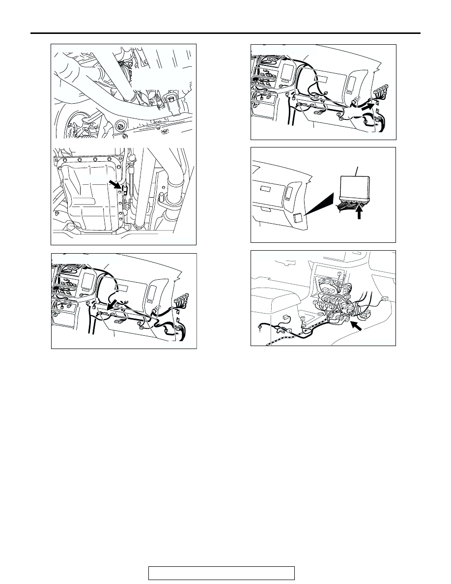
CONNECTOR: C-15
C-15(B)
AD
LEFT BANK
HEATED OXYGEN
SENSOR (REAR)
AK201049
CONNECTOR: D-116
D-116
AC
AK201049
D-14
AB
CONNECTOR: D-14
AK201038AF
CONNECTOR: D-135
PCM
D-135(GR)
AK201052
E-112
AB
CONNECTOR: E-112