Mitsubishi Montero (2004+). Manual - part 1133


  Index      Mitsubishi     Mitsubishi Montero - service repair manual 2004 year


Search            


Content   ..  1131  1132  1133  1134   ..


Mitsubishi Montero (2004+). Manual - part 1133


SHOCK ABSORBER ASSEMBLY

TSB Revision

FRONT SUSPENSION

33A-13

DISASSEMBLY SERVICE POINT

.

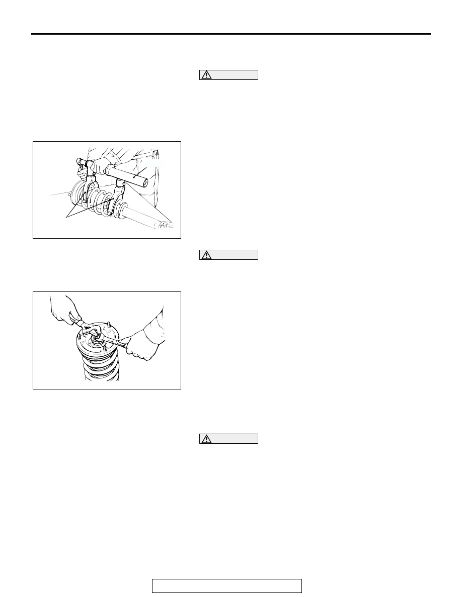
<<A>> SELF-LOCKING NUT REMOVAL

CAUTION

Do not tighten the special tool bolt too tight. The tool will 
be broken if the bolt is tightened over the allowable torque 
74 N

m (55 ft-lb). Install the special tools evenly, and so 

that the maximum length will be attained within the instal-
lation range. Do not use an impact wrench, as it will cause 
the bolt of the special tool to be seized.
1. Use special tools MB991237 and MB991238 to press the 

coil spring.

CAUTION

To prevent the piston rod lock nut inside the strut from 
loosening, do not use an impact wrench when the locking 
nuts are loosened.
2. To prevent the piston rod from turning and unscrew the 

self-locking nut.

ASSEMBLY SERVICE POINTS

.

>>A<< SELF-LOCKING NUT INSTALLATION

CAUTION

• Do not tighten the special tool bolt too tight. The tool 

will be broken if the bolt is tightened over the allowable 
torque 74 N

m(55 ft-lb).

• Install the special tools evenly, and so that the maxi-

mum length will be attained within the installation 
range.

• Do not use an impact wrench, as it will cause the bolt of 

the special tool to be seized.

1. Install special tools MB991237 and MB991238 same as its 

removal and compress the coil spring to install to the shock 
absorber.

ACX00720 AB

MB991238

MB991237

ACX00721 AB

SHOCK ABSORBER ASSEMBLY

TSB Revision

FRONT SUSPENSION

33A-14

2. Align the coil spring lower end and the stepped spring lower 

pad with the shock absorber spring seat stepped part.

.

>>B<< SPRING BRACKET ASSEMBLY INSTALLATION
Install the spring bracket assembly which faces the shock 
absorber as shown in the illustration.

.

>>C<< SELF-LOCKING NUT INSTALLATION
1. Tighten the self-locking nut loosely.

CAUTION

Do not use an impact wrench, as it will cause the bolt of 
the special tool to be seized.
2. Remove special tools MB991237 and MB991238, and then 

tighten the self-locking nut to the specified torque 22 

± 2 N⋅m 

(17 

± 1 ft-lb).

ACX00722 AB

SPRING SEAT

SPRING 
LOWER PAD

COIL 
SPRING END

ACX00723 AB

SPRING
UPPER
BRACKET 
ASSEMBLY

SHOCK
ABSORBER

A

VIEW A

LOWER ARM

TSB Revision

FRONT SUSPENSION

33A-15

LOWER ARM

REMOVAL AND INSTALLATION

M1332001500141

CAUTION

To prevent bushings from breakage, the parts indicated by * should be temporarily tightened, and 
then fully tightened with the vehicle on the ground in the unladen condition.

Required Special Tool:

• MB991897: Ball Joint Remover

Pre-removal Operations
• Drive Shaft Removal (Refer to GROUP 26, Drive Shaft 

P.26-24

).

Post-installation Operations
• Check the dust cover for cracks or damage by pushing it 

with your finger. 

• Drive Shaft Installation (Refer to GROUP 26, Drive Shaft 

P.26-24

).

• Wheel Alignment Check and Adjustment (Refer to 

P.33A-5

).

ACX00724AB

123 

± 14 N

·

m *

91 

± 10 ft-lb *

108 

± 10 N

·

m

80 

± 7 ft-lb

147 

± 29 N

·

m

109 

± 21 ft-lb

162 

± 14 N

·

m *

119 

± 11 ft-lb *

25 

± 4 N

·

m

18 

± 3 ft-lb

123 

± 14 N

·

m *

91 

± 10 ft-lb *

95 

± 11 N

·

m

70 

± 8 ft-lb

11

9

5

3

2

1

6

4

7

8

10

1

5

39 

± 4 N

·

m

29 

± 3 ft-lb

N

N

REMOVAL STEPS

1. COTTER PIN

<<A>> >>A<<

2. LOWER ARM BALL JOINT AND 

KNUCKLE ASSEMBLY 
CONNECTION

<<A>>

3. TIE ROD END AND KNUCKLE 

ASSEMBLY CONNECTION

4. UPPER ARM AND UPPER ARM 

BALL JOINT CONNECTION

5. LOWER ARM BALL JOINT
6. HUB AND KNUCKLE ASSEMBLY

7. SHOCK ABSORBER AND LOWER 

ARM ASSEMBLY CONNECTION

8. BUMP STOPPER
9. LOWER ARM ASSEMBLY AND 

STABILIZER LINK CONNECTION

<<B>>

10. LOWER ARM MOUNTING BOLT
11. LOWER ARM ASSEMBLY

REMOVAL STEPS (Continued)

LOWER ARM

TSB Revision

FRONT SUSPENSION

33A-16

REMOVAL SERVICE POINTS

.

<<A>> TIE ROD END AND KNUCKLE ASSEMBLY/LOWER 
ARM BALL JOINT AND KNUCKLE ASSEMBLY DISCON-
NECTION

CAUTION

• Do not remove the nut from ball joint. Loosen it and use 

special tool MB991897 to avoid possible damage to ball 
joint threads.

• Hang special tool MB991897 with a cord to prevent it 

from falling. 

1. Install special tool MB991897 as shown in the figure.

2. Turn the bolt and knob as necessary to make the jaws of 

special tool MB991897 parallel, tighten the bolt by hand and 
confirm that the jaws are still parallel.
NOTE: When adjusting the jaws in parallel, make sure the 
knob is in the position shown in the figure.

3. Tighten the bolt with a wrench to disconnect the ball joint.

.

<<B>> LOWER ARM MOUNTING BOLT REMOVAL
After making the alignment mark on the bracket and eccentric 
cam bolt, remove them.

INSTALLATION SERVICE POINT

.

>>A<< UPPER ARM BALL JOINT AND KNUCKLE CONNEC-
TION
If the upper arm ball joint is disengaged from the knuckle, 
always renew the upper arm ball joint dust cover and retainer 
by following the procedure below.
1. Unclip the spring ring to removed the dust cover.

AC106820 AB

CORD

BOLT

MB991897

NUT

BALL JOINT

AC106821

KNOB

PARALLEL

BOLT

GOOD

BAD

AB

ACX00725AB

ECCENTRIC 
CAM BOLT


Content   ..  1131  1132  1133  1134   ..