Mitsubishi Montero (2004+). Manual - part 1069


  Index      Mitsubishi     Mitsubishi Montero - service repair manual 2004 year


Search            


Content   ..  1067  1068  1069  1070   ..


Mitsubishi Montero (2004+). Manual - part 1069


ANTI-LOCK BRAKING SYSTEM (ABS) DIAGNOSIS

TSB Revision

ANTI-LOCK BRAKING SYSTEM (ABS)

35B-119

ACX01113AC

ON

OFF

ON

OFF

ON

OFF

ON

OFF

ON

OFF

ON

OFF

ON

OFF

ON

OFF

1s

2s

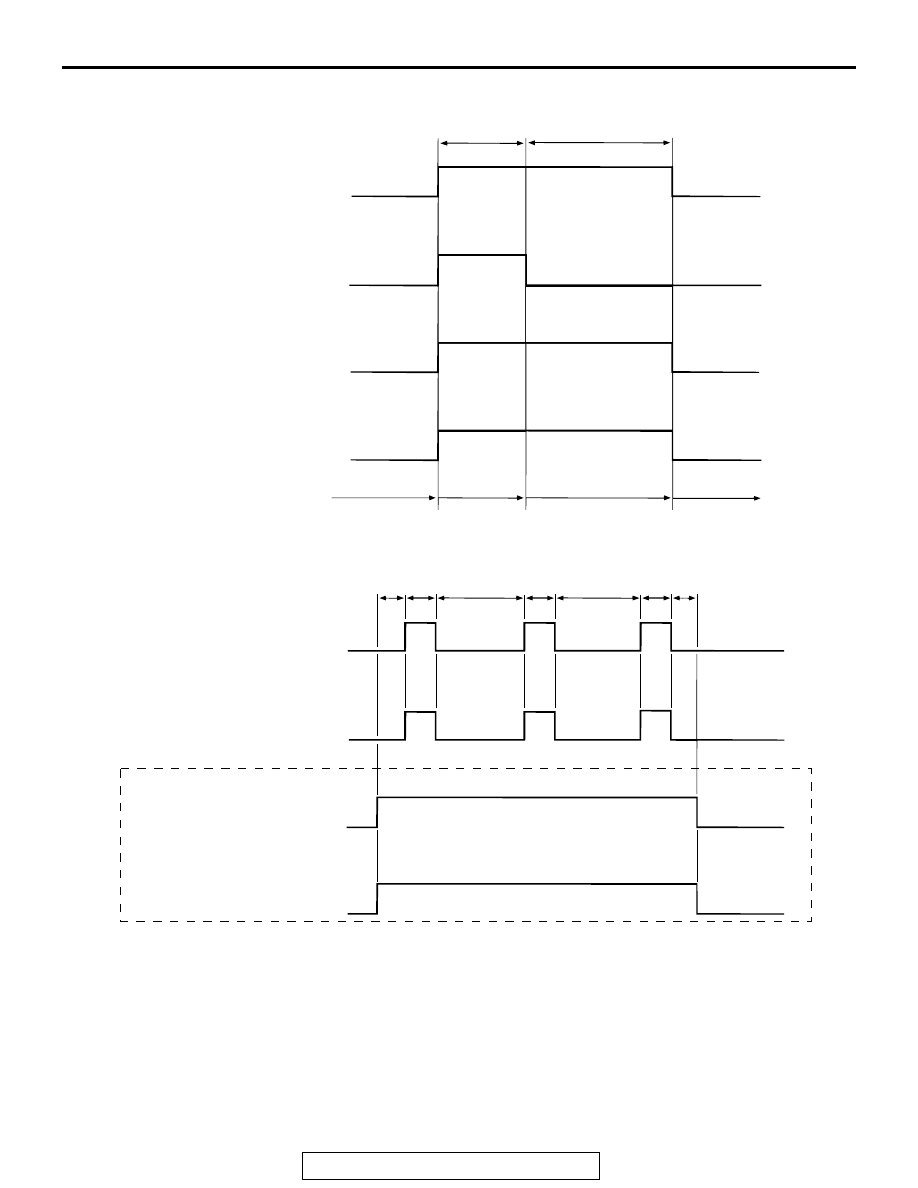
ITEM No. 01 - 04 DRIVE PATTERN

CONTROL SOLENOID 
VALVE IN

CONTROL SOLENOID 
VALVE OUT

SELECT SOLENOID 
VALVE (FR)

SELECT SOLENOID 
VALVE (FL)

CORRESPONDING 
WHEEL BRAKE PRESSURE

INCREASE

DECREASE

HOLD

INCREASE

ITEM No. 09, 10 DRIVE PATTERN

CONTROL SOLENOID 
VALVE OUT (RH)*

CONTROL SOLENOID 
VALVE OUT (LH)*

<ITEM No. 10 ONLY>

SELECT SOLENOID 
VALVE (FR)

SELECT SOLENOID 
VALVE (FL)

NOTE
*: WHEN CARRYING OUT ITEM No. 09, THE FRONT WHEELS ARE DRIVEN, AND WHEN 
    CARRYING OUT ITEM No. 10 THE REAR WHEELS ARE DRIVEN.

0.8s 0.8s

2.5s

0.8s

2.5s

0.8s 0.8s

ANTI-LOCK BRAKING SYSTEM (ABS) DIAGNOSIS

TSB Revision

ANTI-LOCK BRAKING SYSTEM (ABS)

35B-120

CHECK AT M-ASTC-ECU

M1352011800402

TERMINAL VOLTAGE CHECK CHART

NOTE: There are two ECUs with the same shape inside the 
floor console, one above the other. The upper ECU is the 
M-ASTC-ECU. The lower ECU is the transfer-ECU.
NOTE: Do not measure terminal voltage for approximately 
three seconds after the ignition switch is turned "ON." The 
M-ASTC-ECU performs the initial check during that period.
1. Measure the voltages between terminals (4), (12), (56) or 

(64) (ground terminals) and each respective terminal.

2. The terminal layouts are shown in the illustrations.

AC203901

AC204627AY

M-ASTC-ECU

M-ASTC-ECU CONNECTORS

TRANSFER-ECU

CONNECTOR 
TERMINAL NO.

SIGNAL

CHECKING REQUIREMENT

NORMAL 
CONDITION

1

Control solenoid valve 
OUT (Rear right wheel)

Ignition switch: ON

Battery positive 
voltage

2

Control solenoid valve IN 
(Rear right wheel)

Ignition switch: ON

Battery positive 
voltage

3

Control solenoid valve 
OUT (Front left wheel)

Ignition switch: ON

Battery positive 
voltage

5

PI valve

Ignition switch: ON

Battery positive 
voltage

6

Cut valve

Ignition switch: ON

Battery positive 
voltage

7

Select solenoid valve 
(Front right wheel)

Ignition switch: ON

Battery positive 
voltage

8

Select solenoid valve 
(Front left wheel)

Ignition switch: ON

Battery positive 
voltage

10

Control solenoid valve IN 
(Front left wheel)

Ignition switch: ON

Battery positive 
voltage

19

Stoplight switch input

Stoplight switch: ON

Battery positive 
voltage

Stoplight switch: OFF

2 V or less

24

M-ASTC-ECU power 
supply

Ignition switch: ON

Battery positive 
voltage

ANTI-LOCK BRAKING SYSTEM (ABS) DIAGNOSIS

TSB Revision

ANTI-LOCK BRAKING SYSTEM (ABS)

35B-121

42

Control solenoid valve IN 
(Front right wheel)

Ignition switch: ON

Battery positive 
voltage

43

Control solenoid valve 
OUT (Front right wheel)

Ignition switch: ON

Battery positive 
voltage

44

Control solenoid valve IN 
(Rear left)

Ignition switch: ON

Battery positive 
voltage

45

Control solenoid valve 
OUT (Rear light wheel)

Ignition switch: ON

Battery positive 
voltage

50

Pressure sensor power 
supply

Ignition switch: ON

Approximately 5 V

55

Valve relay monitor

Ignition switch: ON

Battery positive 
voltage

59

Pressure sensor

Ignition switch: ON

Approximately 
0.14 

− 4.85 V

62

ABS warning light output Ignition 

switch: ON

When light is switched off

Battery positive 
voltage

When light is illuminated

2 V or less

74

Active skid control 
system operation 
warning light output

Ignition 
switch: ON

When light is switched off

Battery positive 
voltage

When light is illuminated

2 V or less

75

2WD/4WD detection 
switch input

Ignition 
switch: ON

Transfer selector lever 
position: 2H, 4H

Battery positive 
voltage

Transfer selector lever 
position: 4HLc, 4LLc

2 V or less

76

4LLc detection switch 
input

Ignition 
switch: ON

Transfer selector lever 
position: 4LLc

Battery positive 
voltage

Transfer selector lever 
position: 2H, 4H, 4HLc

2 V or less

80

Center differential lock 
switch input

Ignition 
switch: ON

Transfer selector lever 
position: 2H, 4H

Battery positive 
voltage

Transfer selector lever 
position: 4HLc, 4LLc

2 V or less

81

Brake warning light 
output

Ignition 
switch: ON

When light is switched off

2 V or less

When light is illuminated

Battery positive 
voltage

CONNECTOR 
TERMINAL NO.

SIGNAL

CHECKING REQUIREMENT

NORMAL 
CONDITION

ANTI-LOCK BRAKING SYSTEM (ABS) DIAGNOSIS

TSB Revision

ANTI-LOCK BRAKING SYSTEM (ABS)

35B-122

RESISTANCE AND CONTINUITY BETWEEN 
HARNESS-SIDE CONNECTOR TERMINALS

NOTE: There are two ECUs with the same shape inside the 
floor console, one above the other. The upper ECU is the 
M-ASTC-ECU and has a blue connector. The lower ECU is the 
transfer-ECU and has a green connector.
1. Turn the ignition switch to the "LOCK" (OFF) position and 

disconnect the M-ASTC-ECU.

2. Check between the terminals indicated in the table below.
3. The terminal layouts are shown in the illustration.

86

2WD detection switch 
input

Ignition 
switch: ON

Transfer selector lever 
position: 2H

Battery positive 
voltage

Transfer selector lever 
position: 4H, 4HLc, 4LLc

2 V or less

87

4H detection switch input Ignition 

switch: ON

Transfer selector lever 
position: 2H, 4LLc

Battery positive 
voltage

Transfer selector lever 
position: 4H, 4HLc

2 V or less

CONNECTOR 
TERMINAL NO.

SIGNAL

CHECKING REQUIREMENT

NORMAL 
CONDITION

AC203901

AC204627AY

M-ASTC-ECU

M-ASTC-ECU CONNECTORS

TRANSFER-ECU

CONNECTOR 
TERMINAL NO.

SIGNAL

NORMAL CONDITION

30 

− 31

Front-left ABS sensor

1.0 

− 1.5 kΩ

60 

− 61

Rear-right ABS sensor

1.0 

− 1.5 kΩ

46 

− 47

Rear-left ABS sensor

1.0 

− 1.5 kΩ

27 

− 28

Front-right ABS sensor

1.0 

− 1.5 kΩ

− body ground

Ground

Less than 2 ohms

22 

− body ground

Ground

Less than 2 ohms

56 

− body ground

Ground

Less than 2 ohms

64 

− body ground

Ground

Less than 2 ohms


Content   ..  1067  1068  1069  1070   ..