Mitsubishi Montero (2002-2004). Manual - part 603
TSB Revision
DIAGNOSTIC TROUBLE CODE PROCEDURES
13Ac-109
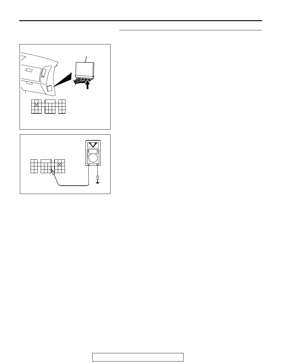
STEP 3. Measure the sensor output voltage at PCM
connector D-135 by backprobing
(1) Do not disconnect the connector D-135.
(2) Start the engine and run at idle.
(3) Measure the voltage between terminal No. 109 and ground
by backprobing.
• Warming up the engine. When the engine is 2,500 r/min,
the output voltage should repeat 0 to 0.8 volt alternately.
(4) Turn the ignition switch to the "LOCK" (OFF) position.
Q: Is the voltage normal?
YES : Go to Step 4.
NO : Go to Step 6.
AK200947
91
92
93
94
95
96
97
98
99
100
101
102
103
104
105
106
107
108
109
110
111
112
113
114
115
116
117
118
119
120
CONNECTOR: D-135
HARNESS CONNECTOR:
COMPONENT SIDE
AB
PCM
D-135(GR)
AK201396
9192
939495
96979899
100 101102103
104
105106
107108109
110111112
113114
115116117
118119120
AB
D-135 HARNESS
CONNECTOR:
HARNESS SIDE