Mitsubishi Montero (2002-2004). Manual - part 366
INPUT SIGNAL PROCEDURES
TSB Revision
SWS INPUT SIGNAL PROCEDURES
54Bc-11
CIRCUIT OPERATION
The ETACS-ECU operates the fog lights according to
signal from the fog light switch.
.
TECHNICAL DESCRIPTION (COMMENT)
If the signal is not normal, the fog lights do not work
normally. If the signal is not normal, the fog light
switch or the ETACS-ECU may be defective.
.
TROUBLESHOOTING HINTS
• The fog light switch may be defective
• The ETACS-ECU may be defective
• The wiring harness or connectors may have
loose, corroded, or damaged terminals, or termi-
nals pushed back in the connector
DIAGNOSIS
Required Special Tools:
• MB991223: Harness Set
• MB991502: Scan Tool (MUT-II)
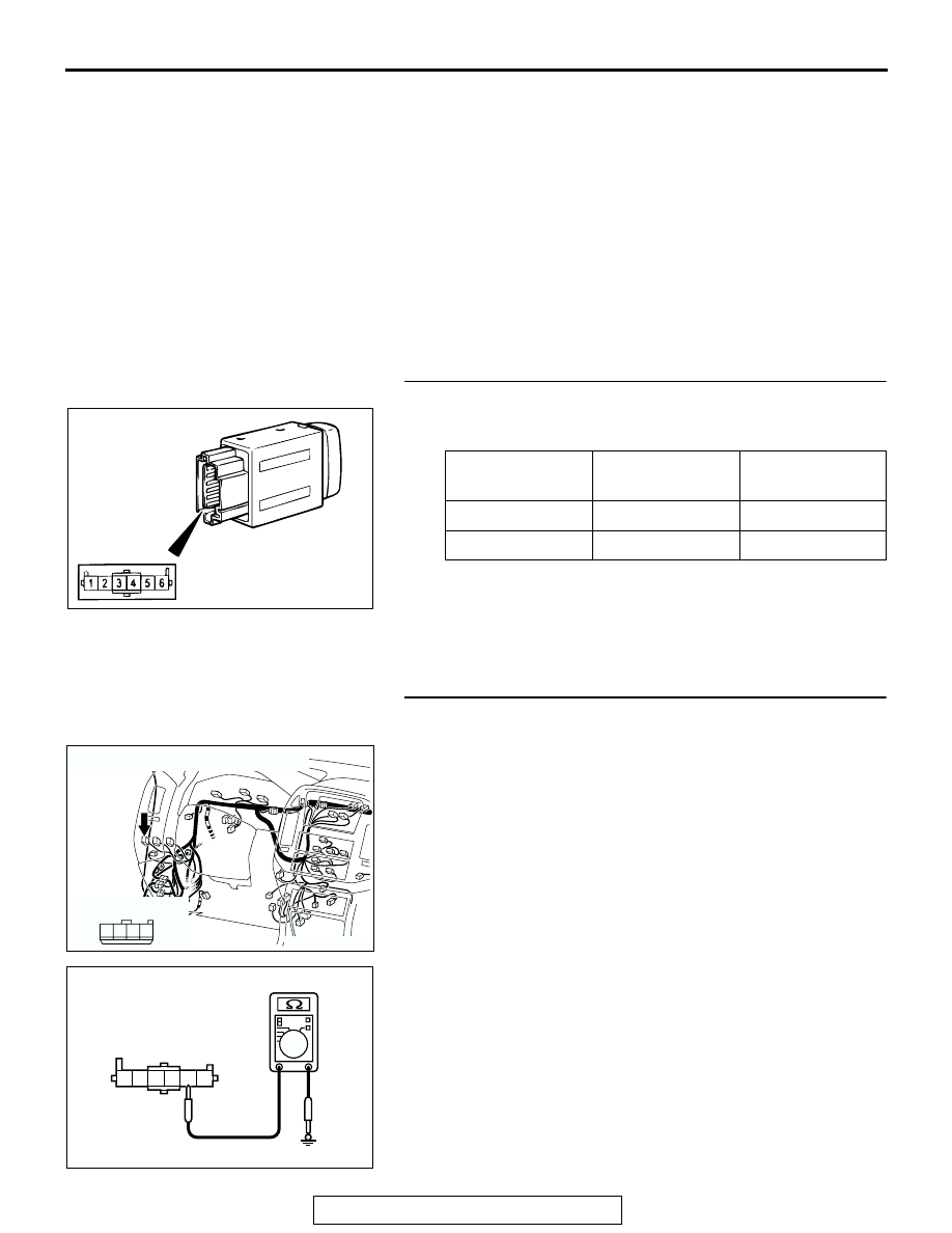
STEP 1. Check the fog light switch.
Remove the fog light switch. Then check continuity between
the switch terminals.
Q: Is the fog light switch in good condition?
YES : Go to Step 2.
NO : Repair the fog light switch. If the for light switch
operates normally, it indicates that a correct signal is
sent from the fog light switch.
STEP 2. Check the ground circuit to the fog light switch.
Test at fog light switch connector D-127.
(1) Disconnect fog light switch connector D-127 and measure
the resistance available at the wiring harness side of the
connector.
(2) Measure the resistance value between terminal 2 and
ground.
• The resistance should equal 2 ohms or less.
Q: Is the measured resistance 2 ohms or less?
YES : Go to Step 5.
NO : Go to Step 3.
SWITCH
POSITION
TESTER
CONNECTION
SPECIFIED
CONDITION
Released
1
− 2
Open circuit
Pressed
1
− 2
Less than 2 ohms
ACX00797
AC204170
CONNECTOR : D-127
HARNESS SIDE
AP
1
2
3
4
D-127
4 3 2 1
5
6
ACX01597AB
CONNECTOR D-127
(HARNESS SIDE)