Mitsubishi Montero (2002-2004). Manual - part 1089


  Index      Mitsubishi     Mitsubishi Montero - service repair manual 2002-2004 year


Search            


Content   ..  1087  1088  1089  1090   ..


Mitsubishi Montero (2002-2004). Manual - part 1089


IGNITION SYSTEM

TSB Revision

ENGINE ELECTRICAL

16-29

2. Ground the spark plug outer electrode (body), and crank the 

engine.
Check that there is an electrical discharge between the 
electrodes at this time.

IGNITION COIL CHECK 

M1163001200153

Check by the following procedure, and replace the coil if there 
is a malfunction.

.

SECONDARY COIL RESISTANCE CHECK
Measure the resistance between the high-voltage terminals of 
the ignition coil.

Standard value: 8.5 

 11.5 k

.

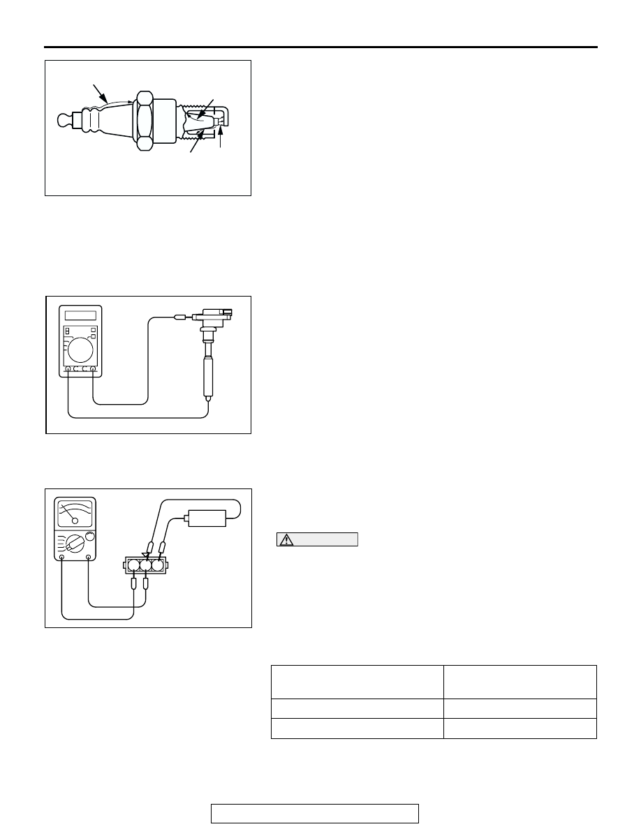
PRIMARY COIL AND IGNITION POWER TRANSISTOR 
CONTINUITY CHECK
NOTE: An analog-type ohmmeter should be used.
NOTE: Connect the negative probe of the ohmmeter to termi-
nal 1.

CAUTION

This test must be performed quickly (in less than 10 sec-
onds) to prevent coil from burning and ignition power tran-
sistor from breaking.
1. Connect and disconnect 1.5 V battery between terminals 2 

and 3, and observe the ohmmeter whether there is 
continuity or not.

2. If results do not agree with the table below, replace the 

primary coil and ignition power transistor assembly.

AKX00277

DEFECTIVE INSULATION

DEFECTIVE INSULATION

DEFECTIVE
INSULATION

GOOD

AB

AKX01264

1.5 V POWER SUPPLY
BETWEEN 2 

 3

CONTINUITY BETWEEN 

 2

Current flowing

Yes

Current not flowing

No

AKX01265AB

1.5 V

1 2 3

+

IGNITION SYSTEM

TSB Revision

ENGINE ELECTRICAL

16-30

SPARK PLUG CABLE RESISTANCE CHECK

M1163001400083

Measure the resistance of the all spark plug leads.
1. Check the cap and coating for cracks.
2. Measure the resistance.

Limit: 19 k

SPARK PLUG CHECK AND CLEANING 

M1163004300212

CAUTION

• Do not attempt to adjust the gap of the iridium plug.
• Cleaning of the iridium plug may result in damage to 

the iridium and platinum tips. Therefore, if carbon 
deposits must be removed, use a plug cleaner and 
complete cleaning within 20 seconds to protect the 
electrode. Do not use a wire brush.

Check the plug gap and replace if the limit is exceeded.

Standard value: 0.7 

 0.8 mm (0.028  0.031 inch)

Limit: 1.0 mm (0.039 inch)

CAMSHAFT POSITION SENSOR AND 
CRANKSHAFT POSITION SENSOR CHECK

M1163002600110

Refer to GROUP 13A, Diagnostic Trouble Code Procedures 

− 

DTC P0335: Crankshaft Position Sensor Circui

P.13Ac-360

.

Refer to GROUP 13A, Diagnostic Trouble Code Procedures 

− 

DTC P0340: Camshaft Position Sensor Circuit 

P.13Ac-377

.

IGNITION SECONDARY VOLTAGE WAVE 
PATTERN CHECK USING A OSCILLOSCOPE

M1163001700028

.

MEASUREMENT METHOD
1. Clamp the spark plug cable (Number 1, 3 or 5) with the 

secondary pickup.
NOTE: Because of the two-cylinder simultaneous ignition 
system, the waves for two cylinders in each group appear 
during wave observation. However, wave observation is car-
ried out for the cylinder (Number 1, 3 or 5) with the spark 
plug cable which has been clamped by the secondary 
pickup.
NOTE: Identification of which cylinder wave pattern is dis-
played can be difficult, but the wave pattern of the cylinder 
which is clamped by the secondary pickup will be stable, so 
this can be used as a reference for identification.

AKX00382

AKX01327AB

IRIDIUM
TIP

PLATINUM
TIP

IGNITION SYSTEM

TSB Revision

ENGINE ELECTRICAL

16-31

2. Clamp the spark plug cable (Number 1, 3 or 5) with the 

trigger pickup.
NOTE: Clamp the same spark plug cable as the one which 
has been clamped by the secondary pickup.

.

STANDARD WAVEPATTERN

Observation Conditions

FUNCTION

SECONDARY

Pattern height

High (or low)

Pattern selector

Raster

Engine revolutions

Curb idle speed

Observation Conditions (Only pattern selector below 
changes from the above conditions.)

Pattern selector

Display

AKX00278

kV

0

SECONDARY

IGNITION

VOLTAGE

WAVE PATTERN

IGNITION VOLTAGE
(POINT D)

SPARK LINE (POINT A)

DWELL SECTION

WAVE DAMPING REDUCTION SECTION (POINT B)

POINT C

TIME

AB

IGNITION SYSTEM

TSB Revision

ENGINE ELECTRICAL

16-32

.

WAVEFORM OBSERVATION POINTS
Point A: 

The height, length and slope of the spark line (refer to 
abnormal waveform examples 1, 2, 3 and 4) show the fol-
lowing trends.

SPARK LINE

PLUG GAP

STATUS OF 
ELECTRODES

COMPRESSION 
FORCE

CONCENTRATION 
OF AIR MIXTURE

IGNITION TIMING

SPARK PLUG 
CABLE

Length

Long

Small

Normal

Low

Rich

Advanced

Leak

Length

Short

Large

Large wear

High

Lean

Retarded

High 
resistance

Height

High

Large

Large wear

High

Lean

Retarded

High 
resistance

Height

Low

Small

Normal

Low

Rich

Advanced

Leak

Slope

Large

Plug is 
fouled

AKX00279

kV

0

SECONDARY
IGNITION
VOLTAGE
WAVE PATTERN

TIME

NO.1 CYLINDER

NO.3 CYLINDER
IGNITION NOISE

NO.6 CYLINDER
IGNITION NOISE

NEUTRAL
SECTION

NO.4 CYLINDER
(WAVE PATTERN
IS DISTURBED)

NO.2 CYLINDER
IGNITION NOISE

NO.5 CYLINDER
IGNITION NOISE

AB


Content   ..  1087  1088  1089  1090   ..