Content .. 1036 1037 1038 1039 ..
Mitsubishi Montero (2002-2004). Manual - part 1038
ANTI-LOCK BRAKING SYSTEM (ABS) DIAGNOSIS
TSB Revision
ANTI-LOCK BRAKING SYSTEM (ABS)
35B-23
STEP 3. Inspect the ABS sensor or ABS rotor.
Refer to
Check items:
• ABS sensor internal resistance: 1.0 − 1.5 kΩ
• Insulation between the ABS sensor body and the connector
terminals
• Toothed ABS rotor check
Q: Is the ABS sensor or ABS rotor damaged?
YES : Replace it and then go to Step 11.
NO : Go to Step 4.
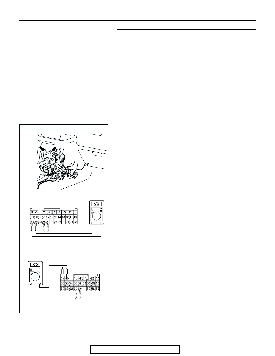
STEP 4. Check ABS sensor circuit at the M-ASTC-ECU
connectors E-119 and E-120.
(1) Disconnect connectors E-119, E-120 and measure at the
harness side.
(2) Measure the resistance between the M-ASTC-ECU
connector E-119 terminals 30 and 31, 27 and 28 or M-
ASTC-ECU connector E-120 terminals 46 and 47, 60 and
61.
Standard Value: 1.0
− 1.5 kΩ
Q: Is the resistance between M-ASTC-ECU connector E-119
terminals 30 and 31, 27 and 28 or M-ASTC-ECU
connector E-120 terminals 46 and 47, 60 and 61 within
the standard value?
When resistances between all terminals are within the
standard value. : Go to Step 9.
When resistance between M-ASTC-ECU connector E-
119 terminals 30 and 31 is not within the standard value.
:
Go to Step 5.
When resistance between M-ASTC-ECU connector E-
119 terminals 27 and 28 is not within the standard value.
:
Go to Step 6.
When resistance between M-ASTC-ECU connector E-
120 terminals 46 and 47 is not within the standard value.
:
Go to Step 7.
When resistance between M-ASTC-ECU connector E-
120 terminals 60 and 61 is not within the standard value.
:
Go to Step 8.
AC204391
CONNECTORS: E-119, E-120
E-119
AB
E-120
E-119 HARNESS CONNECTOR:
COMPONENT SIDE
E-120 HARNESS CONNECTOR:
COMPONENT SIDE