Mitsubishi Montero (2002-2004). Manual - part 37
MANUAL A/C DIAGNOSIS
TSB Revision
HEATER, AIR CONDITIONING AND VENTILATION
55A-11
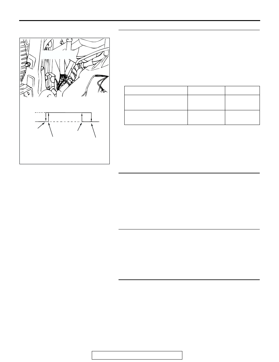
STEP 2. Check the dual pressure switch operation.
(1) Remove the dual pressure switch connector and connect
the high/low pressure side terminals located on the harness
side as shown in the illustration.
(2) Install a gauge manifold to the high-pressure side service
valve of the refrigerant line. (Refer to
(3) When the high/low pressure sides of the dual pressure
switch are at operation pressure (ON) and there is
continuity between the respective terminals.
Q: When the high/low pressure sides of the dual pressure
switch are at operation pressure (ON), is there
continuity between the respective terminals?
YES : Go to Step 3.
NO : Replace the dual pressure switch. Then go to Step 5.
STEP 3. Measure the automatic compressor controller
terminal voltage.
Refer to
Q: Is the automatic compressor controller terminal voltage
correct?
YES : Go to Step 4.
NO : Replace the automatic compressor controller. Then
go to Step 5.
STEP 4. Measure the powertrain control module terminal
voltage.
Refer to GROUP 13A, Diagnosis
− Check at the Powertrain
Control Module (PCM)
Q: Is the voltage correct?
YES : Go to Step 5.
NO : Replace the PCM. Then go to Step 5.
STEP 5. Retest the system.
Q: Does the system produce cool air?
YES : The procedure complete. (If no malfunctions are not
found in all steps, an intermittent malfunction is
suspected. Refer to GROUP 00, How to Use
Troubleshooting/Inspection Service Points
− How to
Cope with Intermittent Malfunction
NO : Go to Step 1.
ITEM
OFF to ON
ON to OFF
Low-pressure side kPa
(psi)
223
± 27 (32.4
± 3.9)
196
± 20 (28.4
± 2.9)
High-pressure side kPa
(psi)
2,550
± 200
(369.9
± 29)
3,140
± 200
(455.5
± 29)
ACX00822
ON
OFF
196 ± 20
(284 ± 2.9)
223 ± 27
(32.4 ± 3.9)
2,550 ± 200
(369.9 ± 29)
3,140 ± 200
(455.5 ± 29)
kPa
(psi)
DUAL PRESSURE
SWITCH
AF