Mitsubishi Galant (2004+). Manual - part 916
MULTIPORT FUEL INJECTION (MFI) DIAGNOSIS
TSB Revision
MULTIPORT FUEL INJECTION (MFI) <2.4L ENGINE>
13A-481
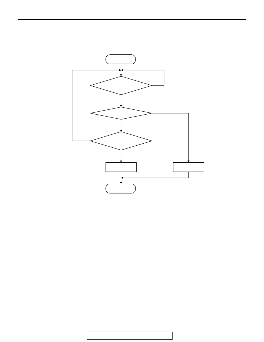
DTC SET CONDITIONS
Logic Flow Chart
Check Conditions
• Engine is running.
Judgment Criteria
• Injector coil surge voltage (battery positive volt-
age + 2 volts) has not been detected for 2 sec-
onds.
.
OBD-II DRIVE CYCLE PATTERN
Refer to Diagnostic Function
− OBD-II Drive Cycle −
Procedure 6
.
.
TROUBLESHOOTING HINTS (The most likely
causes for this code to be set are:)
• No.3 cylinder injector failed.
• Open or shorted No.3 cylinder injector circuit,
harness damage or connector damage.
• PCM failed.
DIAGNOSIS
Required Special Tools:
• MB991958: Scan Tool (MUT-III Sub Assembly)
• MB991824: V.C.I.
• MB991827: USB Cable
• MB991910: Main Harness A
• MB991658: Test Harness
• MB991923: Power Plant ECU Check Harness
START
END
NO
NO
NO
YES
YES
YES
MALFUNCTION
GOOD
MONITORING
CONDITIONS
CONTINUOUS
FAILURE FOR 2secs
INJ. SURGE V
< V
B
+ 2.0 V
AK302031