Mitsubishi Galant (2004+). Manual - part 767


  Index      Mitsubishi     Mitsubishi Galant - service repair manual 2004 year


Search            


Content   ..  765  766  767  768   ..


Mitsubishi Galant (2004+). Manual - part 767


MANUAL A/C DIAGNOSIS

TSB Revision

HEATER, AIR CONDITIONING AND VENTILATION

55A-207

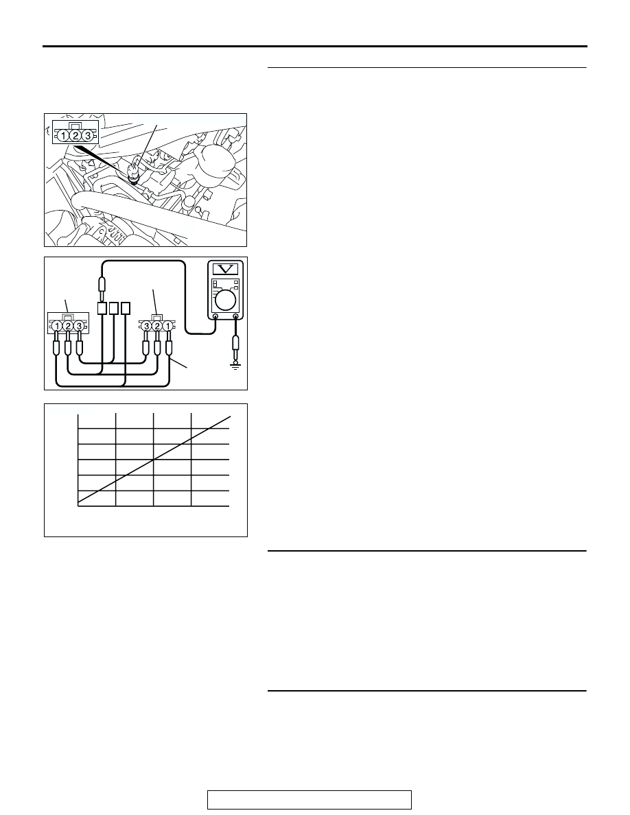
STEP 22. Check the A/C pressure sensor operation.

1. Assemble a gauge manifold on the high pressure service 

valve.

2. Disconnect the A/C pressure sensor connector and connect 

special tool test harness MB991658 as shown in the illustra-
tion.

3. Turn ON the engine and then turn ON the air conditioner 

switch.

4. At this time, check to see that the voltage of A/C pressure 

sensor terminal No. 2 reflects the specifications of the fig-
ure.
NOTE: The allowance shall be defined as 

±

5%.

Q: Is the A/C pressure sensor operating properly?

YES : Go to Step 23.
NO :  Replace the A/C pressure sensor. Check that the air 

conditioning works normally.

STEP 23. Check the refrigerant level.

Use the refrigerant recovery station to remove all of the refrig-
erant, and then calculate the amount of the refrigerant and 
charge it.
Q: Is the refrigerant level correct?

YES : Go to Step 24.
NO :  Correct the refrigerant level (Refer to On-vehicle 

Service 

P.55A-266

). Check that the air conditioning 

works normally. 

STEP 24. Replace the A/C-ECU.
Q: Does the A/C operate normally?

YES : The procedure is complete.
NO :  Replace the powertrain control module. Check that 

the air conditioning works normally. 

AC305034

A/C PRESSURE SENSOR

AD

AC307368

A/C 
PRESSURE 
SENSOR 
SIDE

MB991658

AB

HARNESS SIDE

AC208297AB

REFRIGERANT PRESSURE (MPa)

OUTPUT VOLTAGE 

(V)

0

1

2

3

5

4

1

2

3

MANUAL A/C DIAGNOSIS

TSB Revision

HEATER, AIR CONDITIONING AND VENTILATION

55A-208

INSPECTION PROCEDURE 5: Front Blower Fan and Motor do not Turn.

IGNITION 
SWITCH (IG2)

FUSIBLE
LINK

1

JUNCTION
BLOCK

BLOWER
RELAY

FRONT
BLOWER
MOTOR

POWER
TRANSISTOR

A/C-ECU

Blower Motor Circuit

MANUAL A/C DIAGNOSIS

TSB Revision

HEATER, AIR CONDITIONING AND VENTILATION

55A-209

.

CIRCUIT OPERATION
If the blower motor does not operate, the blower 
relay system is suspected.

.

TROUBLESHOOTING HINTS

• Malfunction of the front blower relay

• Malfunction of the power transistor

• Malfunction of the front blower motor

• Malfunction of the A/C-ECU

• Damaged harness wires or connectors

DIAGNOSIS

Required Special Tool:

• MB991223: Test Harness Set

AC305015AH

FUSIBLE LINK (1)

FUSIBLE LINKS 
NO.1

AC305233BP

CONNECTORS: C-14, C-115

C-14

C-115

AC305231

CONNECTOR: C-29

AH

AC305415BD

CONNECTORS: C-202, C-211, C-215, C-216

JUNCTION BLOCK 
(FRONT VIEW)

C-216 (B)

C-215

C-202

C-211

MANUAL A/C DIAGNOSIS

TSB Revision

HEATER, AIR CONDITIONING AND VENTILATION

55A-210

STEP 1. Check blower motor connector C-115 and 
A/C-ECU connector C-15 for loose, corroded or damaged 
terminals, or terminals pushed back in the connector.

Q: Are blower motor connector C-115 and A/C-ECU 

connector C-15 in good condition?
YES : 
Go to Step 2.
NO :  Repair or replace the connector. Refer to GROUP 

00E, Harness Connector Inspection 

P.00E-2

.The 

blower motor should operate normally.

AC305234

CONNECTORS: C-15, C-115

HARNESS SIDE

C-15

C-115

HARNESS SIDE

C-115

C-15 (B)

AQ


Content   ..  765  766  767  768   ..