Mitsubishi Galant (2004+). Manual - part 227


  Index      Mitsubishi     Mitsubishi Galant - service repair manual 2004 year


Search            


Content   ..  225  226  227  228   ..


Mitsubishi Galant (2004+). Manual - part 227


SYMPTOM PROCEDURES

TSB Revision

SIMPLIFIED WIRING SYSTEM (SWS)

54B-99

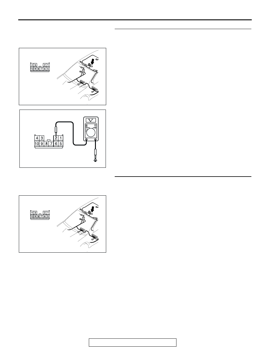
STEP 4. Check the ignition switch (IG2) circuit to the 
sunroof motor assembly. Measure the voltage at sunroof 
motor assembly connector D-04.

(1) Disconnect sunroof motor assembly connector D-04 and 

measure the voltage available at the wiring harness side of 
the connector.

(2) Turn the ignition switch to the "ON" position.

(3) Measure the voltage between terminal 2 and ground.

• The voltage should measure approximately 12 volts 

(battery positive voltage).

Q: Is the measured voltage approximately 12 volts (battery 

positive voltage)?
YES : 
Go to Step 6.
NO :  Go to Step 5.

STEP 5. Check the wiring harness between sunroof motor 
assembly connector D-04 (terminal 2) and ignition switch 

(IG2).

AC305264

AC305264

AM

CONNECTOR: D-04

HARNESS SIDE

AC209365 FH

CONNECTOR D-04
(HARNESS SIDE)

AC305264

AC305264

AM

CONNECTOR: D-04

HARNESS SIDE

SYMPTOM PROCEDURES

TSB Revision

SIMPLIFIED WIRING SYSTEM (SWS)

54B-100

NOTE: Also check junction block connectors C-215 and C-205 
for loose, corroded, or damaged terminals, or terminals pushed 
back in the connector. If junction block connector C-215 or 
C-205 is damaged, repair or replace the damaged compo-
nent(s) as described in GROUP 00E, Harness Connector 
Inspection 

P.00E-2

.

Q: Is the wiring harness between sunroof motor assembly 

connector D-04 (terminal 2) and the ignition switch (IG2) 
in good condition?
YES : 
No action is necessary and testing is complete.
NO :  The wiring harness may be damaged or the 

connector(s) may have loose, corroded or damaged 
terminals, or terminals pushed back in the connector. 
Repair the wiring harness as necessary. The system 
should communicate with the sunroof-ECU normally.

STEP 6. Check the ground circuit to the sunroof motor 
assembly. Measure the resistance at sunroof motor 
assembly connector D-04.

(1) Disconnect sunroof motor assembly connector D-04 and 

measure the resistance available at the wiring harness side 

of the connector.

(2) Measure the resistance value between terminal 5 and 

ground.

• The resistance should be 2 ohms or less.

Q: Is the measured resistance 2 ohms or less?

YES : Go to Step 8.
NO :  Go to Step 7.

AC305416

AC305416

C-205

HARNESS SIDE

HARNESS SIDE

C-215

CONNECTORS: C-205,C-215

AH

C-205

C-215

JUNCTION BLOCK

(FRONT VIEW)

AC305264

AC305264

AM

CONNECTOR: D-04

HARNESS SIDE

AC209364HG

CONNECTOR D-04
(HARNESS SIDE)

SYMPTOM PROCEDURES

TSB Revision

SIMPLIFIED WIRING SYSTEM (SWS)

54B-101

STEP 7. Check the wiring harness between sunroof motor 
assembly connector D-04 (terminal 5) and ground.

Q: Is the wiring harness between sunroof motor assembly 

connector D-04 (terminal 5) and ground in good 
condition?
YES : 
No action is necessary and testing is complete.
NO :  The wiring harness may be damaged or the 

connector(s) may have loose, corroded or damaged 
terminals, or terminals pushed back in the connector. 
Repair the wiring harness as necessary. The system 
should communicate with the sunroof-ECU normally.

STEP 8. Check ETACS-ECU connector C-218 for loose, 
corroded or damaged terminals, or terminals pushed back 
in the connector.

Q: Is ETACS-ECU connector C-218 in good condition?

YES : Go to Step 9.
NO :  Repair or replace the damaged component(s). Refer 

to GROUP 00E, Harness Connector Inspection 

P.00E-2

. The system should communicate with the 

sunroof-ECU normally.

STEP 9. Check the wiring harness between sunroof motor 
assembly connector D-04 (terminal 10) and ETACS-ECU 

connector C-218 (terminal 59).

AC305264

AC305264

AM

CONNECTOR: D-04

HARNESS SIDE

AC305413AN

CONNECTOR: C-218

JUNCTION BLOCK
(REAR VIEW)

C-218 (GR)

HARNESS SIDE

51

52

53

54

55

56

57

58

59

60

61

62

63

64

65

66

67

68

69

70

71

72

73

74

AC305413AN

CONNECTOR: C-218

JUNCTION BLOCK
(REAR VIEW)

C-218 (GR)

HARNESS SIDE

51

52

53

54

55

56

57

58

59

60

61

62

63

64

65

66

67

68

69

70

71

72

73

74

AC305264

AC305264

AM

CONNECTOR: D-04

HARNESS SIDE

SYMPTOM PROCEDURES

TSB Revision

SIMPLIFIED WIRING SYSTEM (SWS)

54B-102

NOTE: Also check intermediate connector C-27 and joint con-
nector C-03 for loose, corroded, or damaged terminals, or ter-
minals pushed back in the connector. If intermediate connector 
C-27 or joint connector C-03 is damaged, repair or replace the 
damaged component(s) as described in GROUP 00E, Harness 
Connector Inspection 

P.00E-2

.

Q: Is the wiring harness between sunroof motor assembly 

connector D-04 (terminal 10) and ETACS-ECU connector 
C-218 (terminal 59) in good condition?
YES : 
Go to Step 10.
NO :  The wiring harness may be damaged or the 

connector(s) may have loose, corroded or damaged 
terminals, or terminals pushed back in the connector. 
Repair the wiring harness as necessary. The system 
should communicate with the sunroof-ECU normally.

STEP 10. Replace the sunroof motor assembly.
(1) Replace the sunroof motor assembly.
(2) The system should communicate with the sunroof-ECU 

normally.

Q: Can the system communicate with the sunroof-ECU?

YES : No action is necessary and testing is complete.
NO :  Replace the ETACS-ECU. The system should 

communicate with the sunroof-ECU normally.

AC305232

AC305232

CONNECTORS: C-03, C-27

AI

C-03

C-27

C-27

C-03 HARNESS SIDE


Content   ..  225  226  227  228   ..