Mitsubishi Pajero Pinin. Manual - part 155
ENGINE ELECTRICAL –
Ignition System
16-14
IGNITION SYSTEM
GENERAL
OUTLINE OF CHANGES
The following service procedures have been established to correspond to the addition of vehicles with
4G9-MPI engine. Other service procedures are the same as for the 4G9-GDI engine.
GENERAL INFORMATION
This system is equipped with two ignition coils (A
and B) with built-in power transistors for the No.
1 and No. 4 cylinders and the No. 2 and No. 3
cylinders respectively.
Interruption of the primary current flowing in the
primary side of ignition coil A generates a high
voltage in the secondary side of ignition coil A.
The high voltage thus generated is applied to the
spark plugs of No. 1 and No. 4 cylinders to generate
sparks. At the time that the sparks are generated
at both spark plugs, if one cylinder is at the
compression stroke, the other cylinder is at the
exhaust stroke, so that ignition of the compressed
air/fuel mixture occurs only for the cylinder which
is at the compression stroke.
In the same way, when the primary current flowing
in ignition coil B is interrupted, the high voltage
thus generated is applied to the spark plugs of No.
2 and No. 3 cylinders.
The engine-ECU turns the two power transistors
inside the ignition coils alternately on and off. This
causes the primary currents in the ignition coils to
be alternately interrupted and allowed to flow to
fire the cylinders in the order 1– 3– 4– 2.
The engine-ECU determines which ignition coil
should be controlled by means of the signals from
the camshaft position sensor which is incorporated
in the camshaft and from the crank angle sensor
which is incorporated in the crankshaft. It also
detects the crankshaft position in order to provide
ignition at the most appropriate timing in response
to the engine operation conditions. It also detects
the crankshaft position in order to provide ignition
at the most appropriate timing in response to the
engine operation conditions.
When the engine is cold or operated at high altitudes,
the ignition timing is slightly advanced to provide
optimum performance.
When the automatic transmission shifts gears, the
ignition timing is also retarded in order to reduce
output torque, thereby alleviating shifting shocks.
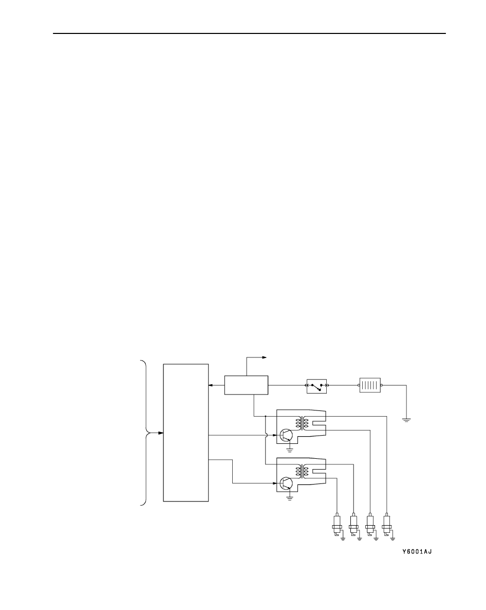
SYSTEM DIAGRAM
Intake air temperature sensor
Engine coolant temperature
sensor
Camshaft position sensor
Crank angle sensor
Ignition switch-ST
Vehicle speed sensor
Engine-ECU
Ignition coil A
Ignition coil B
Ignition switch
Spark plug
Battery
Cylinder
Detonation sensor
Air flow sensor
Barometric pressure sensor
Inhibitor switch
Ignition
failure
sensor
To tachometer
No.3
2
4
1