Mitsubishi Space Star. Manual - part 48
GDI –
Troubleshooting
13A-119
INJECTORS AND INJECTOR OPEN CIRCUIT CHECK
SIGNAL
The measurement method has been changed from the previous
description.
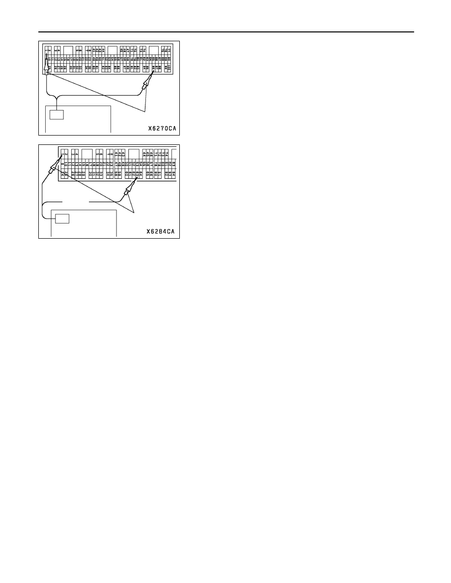
Measurement Method
<Vehicles with M/T>
1.
Connect the analyzer special patterns pickup to terminal
1 (No. 1 injector) of the engine-ECU connector.
2.
Connect the analyzer special patterns pickup to terminal
96 (injector open circuit check signal) of the engine-ECU
connector.
3.
After checking terminal 1, check terminal 9 (No. 2 injector),
terminal 24 (No. 3 injector) and terminal 2 (No. 4 injector).
<Vehicles with A/T>
1.
Connect the analyzer special patterns pickup to terminal
1 (No. 1 injector) of the engine-A/T-ECU connector.
2.
Connect the analyzer special patterns pickup to terminal
63 (injector open circuit check signal) of the
engine-A/T-ECU connector.
3.
After checking terminal 1, check terminal 9 (No. 2 injector),
terminal 24 (No. 3 injector) and terminal 2 (No. 4 injector).
IGNITION COIL AND POWER TRANSISTOR
(Power transistor control signal)
The followings have been changed from the previous
description.
Alternate Method (Test harness not available)
<Vehicles with M/T>
Connect the analyzer special patterns pickup to engine-ECU
terminal 3 (No. 1 ignition coil), terminal 13 (No. 2 ignition
coil), terminal 12 (No. 3 ignition coil) and terminal 4 (No. 4
ignition coil) respectively.
<Vehicles with A/T>
Connect the analyzer special patterns pickup to
engine-A/T-ECU terminal 11 (No. 1 ignition coil), terminal 12
(No. 2 ignition coil), terminal 31 (No. 3 ignition coil) and terminal
30 (No. 4 ignition coil) respectively.
Special patterns
pickup
Analyzer
Special patterns
pickup
Analyzer