Mitsubishi Lancer (4A9 engine). Manual - part 131


  Index      Mitsubishi     Mitsubishi Lancer (4A9 engine) 12GS41 & 44S - service repair manual


Search            


Content   ..  129  130  131  132   ..


Mitsubishi Lancer (4A9 engine). Manual - part 131


FOG LAMP

CHASSIS ELECTRICAL

54A-186

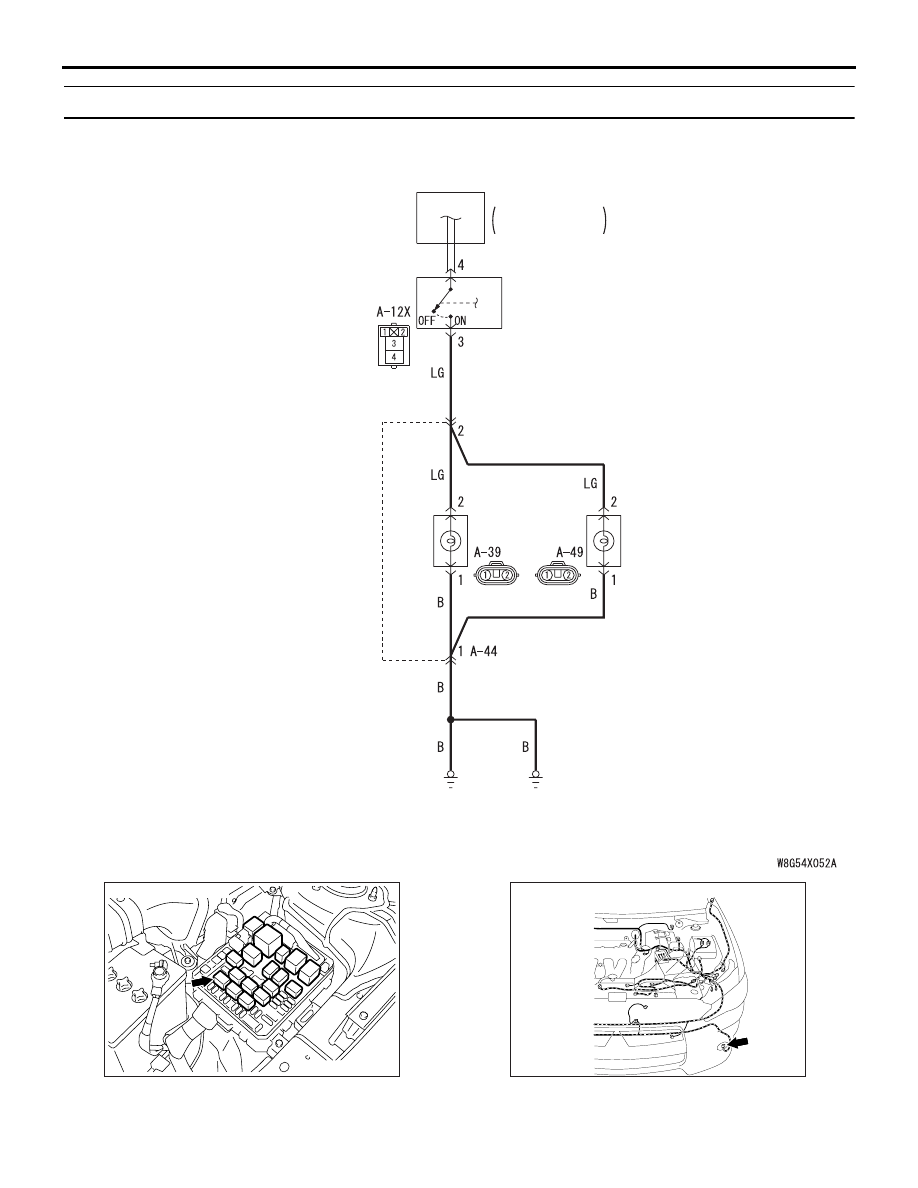
Inspection Procedure 2: One of the front fog lamps does not illuminate.

Wire colour code 
B : Black     LG : Light green     G : Green     L : Blue     W : White     Y : Yellow     SB : Sky blue 
BR : Brown     O : Orange     GR : Grey     R : Red     P : Pink     V : Violet     PU : Purple     SI : Silver

Front Fog Lamp Circuit

FRONT FOG
LAMP RELAY

RELAY BOX

ENGINE 
COMPARTMENT

      FRONT 
      FOG LAMP
(LH)              (RH)

AC612144

AC801941

AI

Connector: A-12X

AC612690

BF

Connector: A-39

A-39 (B)

FOG LAMP

CHASSIS ELECTRICAL

54A-187

COMMENTS ON TROUBLE SYMPTOM
When one of the front fog lamps does not illuminate, 
the wiring harness, connector(s), or bulb(s) may 
have a problem, or the fuse may be burned out.

PROBABLE CAUSES

• Malfunction of bulbs

• Damaged harness wires and connectors

DIAGNOSIS PROCEDURE

STEP 1. Connector check: A-39 (LH) or A-49 (RH) 
front fog lamp connector

Q: Is the check result normal?

YES : 

Go to Step 2.

NO : 

Repair the defective connector.

STEP 2. Bulb check
Check the bulb(s) of the lamp that does not illumi-
nate.

Q: Is the check result normal?

YES : 

Go to Step 3.

NO : 

Replace the bulb(s) of the lamp that does 
not illuminate.

STEP 3. Resistance measurement at the A-39 
(LH) or A-49 (RH) front fog lamp connector
(1) Disconnect the connector, and measure at the 

wiring harness side.

(2) Measure the resistance between the connector of 

lamp which does not illuminate and the body 
earth.

• Measure the resistance between the A-39 

(LH) front fog lamp connector terminal No. 1 
and the body earth.

• Measure the resistance between the A-49 

(RH) front fog lamp connector terminal No. 1 
and the body earth.

OK: Continuity exists (2 

 or less)

Q: Is the check result normal?

YES : 

Go to Step 5.

NO : 

Go to Step 4.

STEP 4. Wiring harness check between the A-39 
(LH) or A-49 (RH) front fog lamp connector 
terminal No. 1 and body earth
NOTE: Before the wiring harness check, check the 
intermediate connector A-44, and then repair that if 
necessary.

• Check the earth wires for open circuit.

Q: Is the check result normal?

YES : 

Go to Step 7.

NO : 

Repair the wiring harness.

STEP 5. Connector check: A-12X front fog lamp 
relay connector

Q: Is the check result normal?

YES : 

Go to Step 6.

NO : 

Repair the defective connector.

STEP 6. Wiring harness check between the A-12X 
front fog lamp relay connector terminal No. 3 and 
the A-39 front fog lamp (LH) or A-49 front fog 
lamp (RH) connector terminal No. 2
NOTE: Before the wiring harness check, check the 
intermediate connector A-44, and then repair that if 
necessary.

• Check the output lines for open circuit.

Q: Is the check result normal?

YES : 

Go to Step 7.

NO : 

Repair the wiring harness.

STEP 7. Retest the system
Check that the front fog lamps illuminate normally.

Q: Is the check result normal?

YES : 

The trouble can be an intermittent 

malfunction (Refer to GROUP 00 

− How to 

use Troubleshooting/inspection Service 
Points 

− How to Cope with Intermittent 

Malfunction ).

NO : 

Go to Step 1.

AC612691

AL

Connector: A-49

A-49 (B)

FOG LAMP

CHASSIS ELECTRICAL

54A-188

Inspection Procedure 3: The front fog lamp indicator does not illuminate normally.

CAUTION

Whenever the ECU is replaced, ensure that the power supply circuit, the earth circuit and the commu-
nication circuit are normal.

COMMENTS ON TROUBLE SYMPTOM
If the front fog lamp indicator does not illuminate nor-
mally, connector(s), wiring harness in the CAN bus 
lines, the ETACS-ECU or the combination meter may 
be defective.

PROBABLE CAUSES

• Malfunction of the ETACS-ECU

• Malfunction of the combination meter

• Damaged harness wires and connectors

DIAGNOSIS PROCEDURE

STEP 1. Check the front fog lamps
When the front fog lamp switch is operated, check 
that the front fog lamps illuminate/go off normally.

Q: Is the check result normal?

YES : 

Go to Step 2.

NO : 

First, repair the front fog lamps (Refer to 
trouble symptom chart ).

STEP 2. M.U.T.-III CAN bus diagnostics
Use the M.U.T.-III to diagnose the CAN bus lines.

Q: Is the check result normal?

YES : 

Go to Step 3.

NO : 

Repair the CAN bus line (Refer to GROUP 
54C 

− Troubleshooting ).

STEP 3. M.U.T.-III diagnosis code
Check if diagnosis code is set to the ETACS-ECU.

Q: Is the diagnosis code set?

YES : 

Troubleshoot the ETACS-ECU. Refer to .

NO : 

Go to Step 4.

STEP 4. M.U.T.-III other system actuator test
Perform the actuator test for the combination meter, 
and check that the front fog lamp indicator illumi-
nates (Refer to Combination Meter ).

Q: Is the check result normal?

YES : 

Replace the ETACS-ECU.

NO : 

Replace the combination meter.

INPUT SIGNAL

ETACS-ECU

COMBINATION
METER

CAN COMMUNICATION LINE
(CAN_L LINE)

CAN COMMUNICATION LINE
(CAN_H LINE)

Front Fog Lamp Indicator Lamp Circuit

FRONT FOG LAMP
SWITCH

FOG LAMP

CHASSIS ELECTRICAL

54A-189

Inspection Procedure 4: The rear fog lamp do not illuminate normally.

CAUTION

Whenever the ECU is replaced, ensure that the power supply circuit, the earth circuit and the commu-
nication circuit are normal.

CIRCUIT OPERATION
If the rear fog lamps do not illuminate normally, the 
input signal circuit(s) below or the ETACS-ECU may 
be defective.

• Tail lamp switch

• Headlamp switch

• Fog lamp switch

• Option coding information

COMMENTS ON TROUBLE SYMPTOM
When the rear fog lamps do not illuminate normally, 
the mentioned input signal circuit(s) or ETACS-ECU 
may be defective.

PROBABLE CAUSES

• Malfunction of column switch

• Malfunction of the ETACS-ECU

• Damaged harness wires and connectors

DIAGNOSIS PROCEDURE

STEP 1. ETACS-ECU coding data check
(1) Operate the M.U.T.-III to read the ETACS-ECU 

option coding information (Refer to GROUP 00 

− 

Coding List ).

(2) Check that the "Rear fog lamp" is set to 

"Present."

Q: Is the check result normal?

YES : 

Go to Step 2.

NO : 

Operate the M.U.T.-III to set the option 
coding "Rear fog lamp" to "Present," and 
check the trouble symptom.

STEP 2. Check the operation of the position 
lamps and the headlamps.
Check that the position lamps and the headlamps 
illuminate normally.

Q: Is the check result normal?

YES : 

Go to Step 3.

NO : 

Check the position lamps and the 
headlamps (Refer to trouble symptom chart 
).

STEP 3. M.U.T.-III diagnosis code
Check if diagnosis code is set to the ETACS-ECU.

Q: Is the diagnosis code set?

YES : 

Troubleshoot the ETACS-ECU. Refer to .

NO : 

Go to Step 4.

ACA00886

AX

ETACS-ECU

Connector: C-311 <LHD>

ACA00887

AW

ETACS-ECU

Connector: C-311 <RHD>

ACA00901AG

F-21 (GR)

Connectors: F-21, F-35 <LANCER>

F-35 (GR)

AC801775BX

Connector: F-21 <LANCER SPORTBACK>


Content   ..  129  130  131  132   ..