Mitsubishi Lancer Evolution X. Manual - part 290
MULTIPORT FUEL INJECTION (MFI) DIAGNOSIS
TSB Revision
MULTIPORT FUEL INJECTION (MFI)
13A-225
DTC SET CONDITIONS
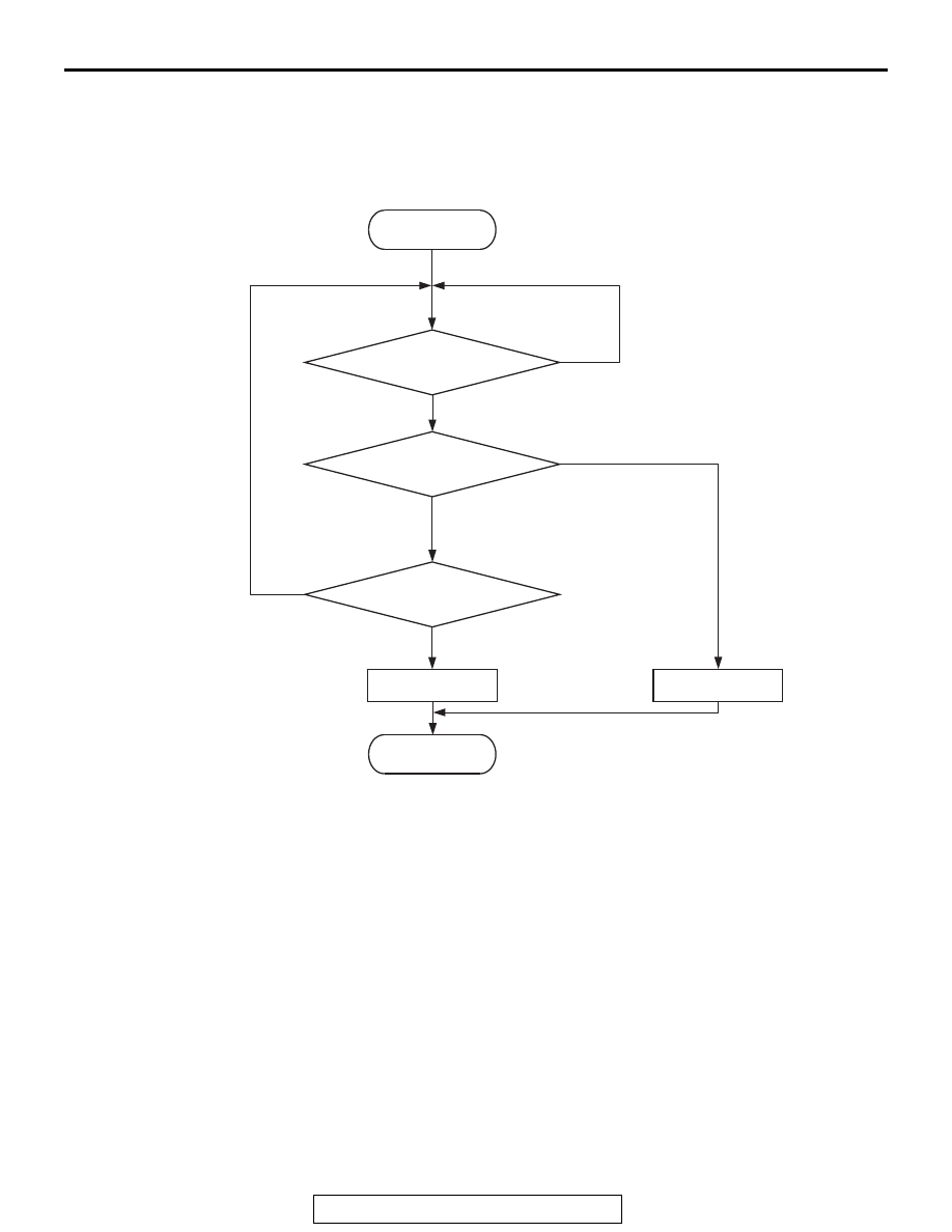
Logic Flow Chart
.
Check Conditions
• Heated oxygen sensor offset voltage is between
0.4 and 0.6 volt.
• Battery positive voltage is between 11 and 16.5
volts.
• More than 330 seconds have passed since the
engine starting sequence was completed.
Judgement Criterion
• Heated oxygen sensor (front) output voltage is
lower than 0.2 volt for 2 seconds.
.
FAIL-SAFE AND BACKUP FUNCTION
• None
.
OBD-II DRIVE CYCLE PATTERN
Refer to Diagnostic Function − OBD-II Drive Cycle −
Pattern 22
.
.
TROUBLESHOOTING HINTS (The most
likely causes for this code to be set are:)
• Heated oxygen sensor (front) failed.
• Open or shorted circuit in heated oxygen sensor
(front) output line, or harness damage.
• Open circuit in heated oxygen sensor (front)
ground line, or harness damage.
• Connector damage.
• ECM failed.
End
Malfunction
No
No
No
2secs have passed?
Output voltage
< 0.2V
Good
AK604321
Start
Yes
Yes
Yes
Monitoring
conditions