Mitsubishi Lancer Evolution X. Manual - part 221
STABILIZER BAR
TSB Revision
FRONT SUSPENSION
33-17
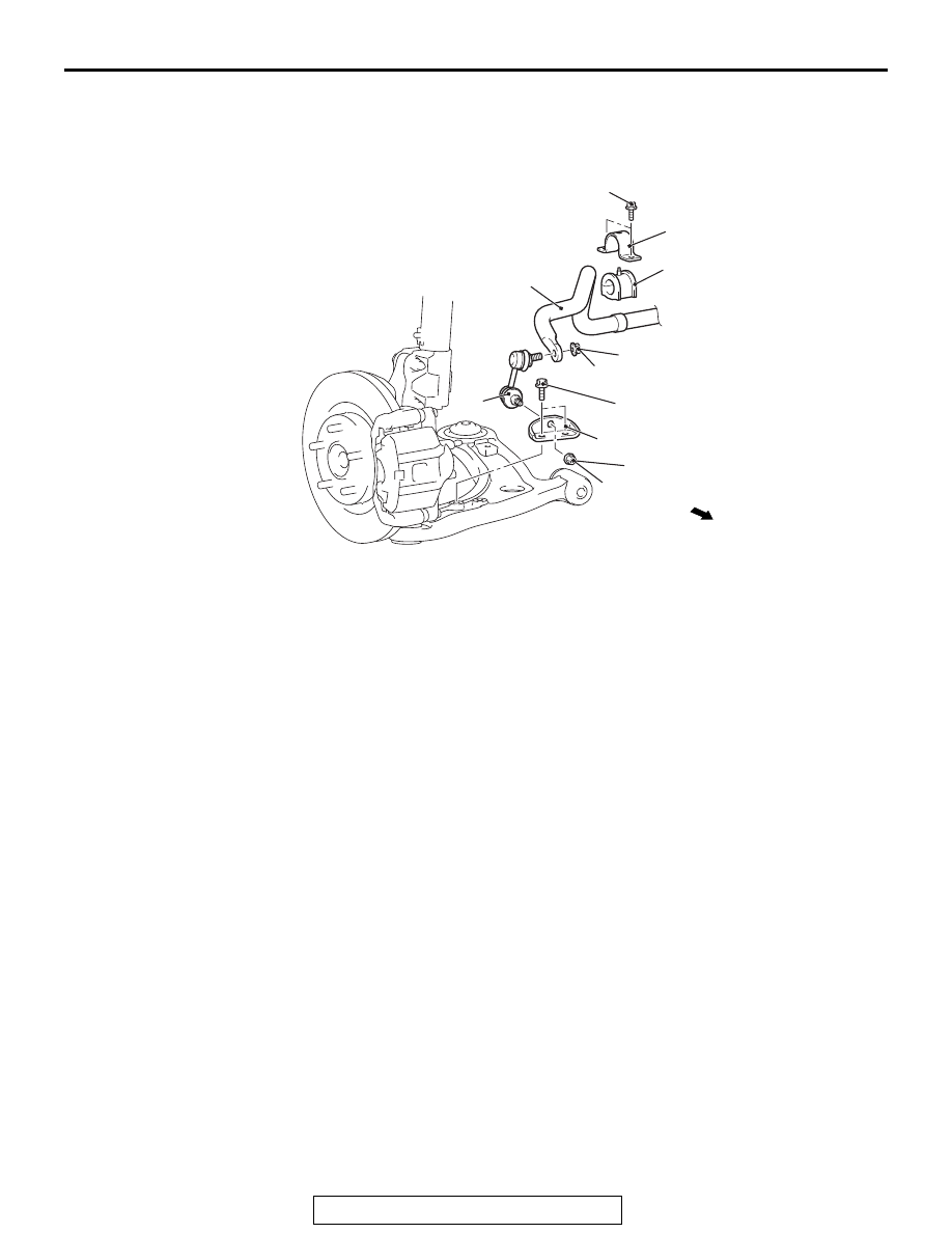
STABILIZER BAR
REMOVAL AND INSTALLATION
M1332001900804
AC704986 AB
31 ± 4 N·m
23 ± 3 ft-lb
1
3
5
6
4
39 ± 6 N·m
29 ± 4 ft-lb
7
Vehicle front side
2
39 ± 5 N·m
29 ± 4 ft-lb
39 ± 6 N·m
29 ± 4 ft-lb
Removal steps
1.
Stabilizer nut
2.
Stabilizer bracket
3.
Stabilizer nut
4.
Stabilizer link
•
Front axle crossmember
(Refer to GROUP 32 − Rear
roll stopper and crossmember
).
5.
Stabilizer bar bracket
>>A<<
6.
Stabilizer bushing
7.
Stabilizer bar
Removal steps (Continued)