Mitsubishi Lancer Evolution IX. Manual - part 573
UPPER ARM ASSEMBLY
REAR SUSPENSION
34-7
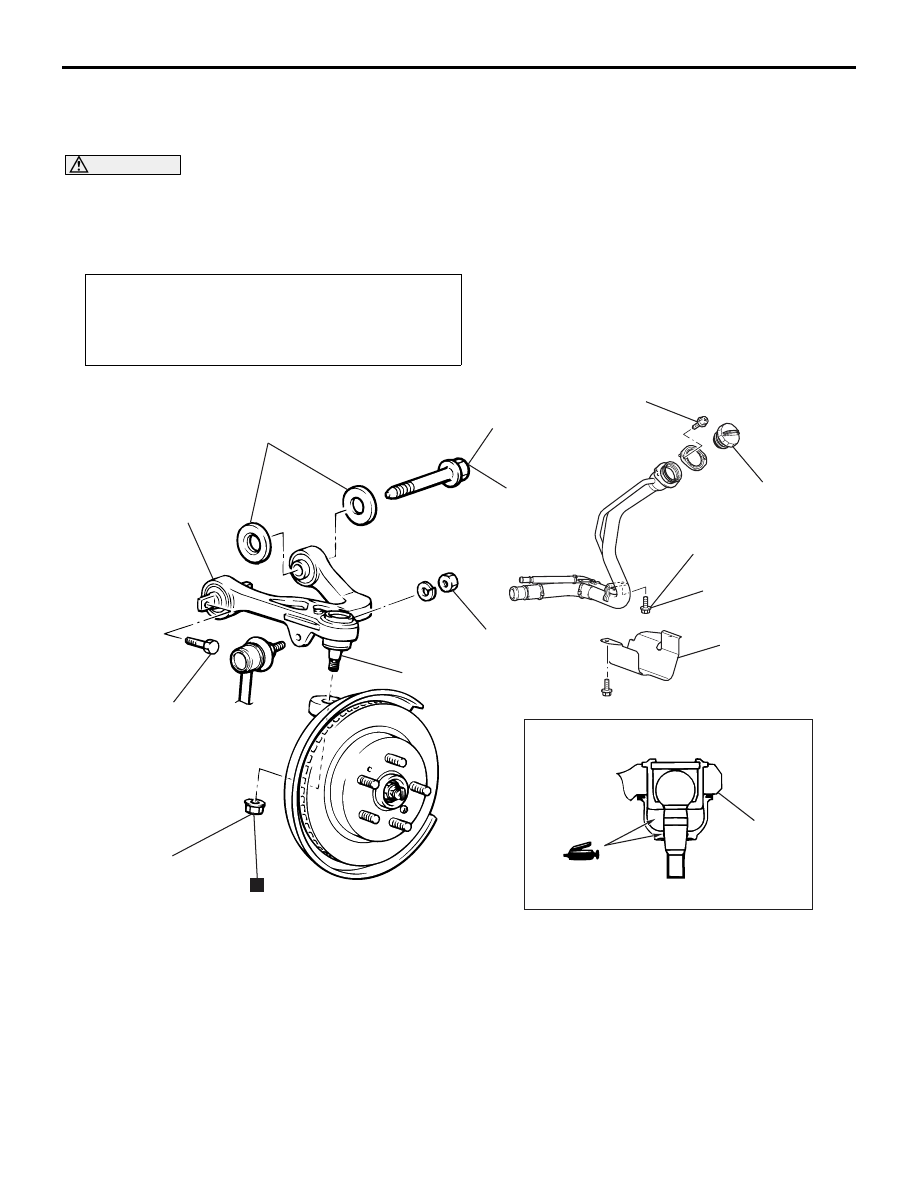
UPPER ARM ASSEMBLY
REMOVAL AND INSTALLATION
M1341003600335
CAUTION
• During maintenance, take care not to contact the parts or tools to the caliper, because the paint of
caliper will be scratched. And if there is brake fluid on the caliper, wipe out quickly.
•
Post-installation Operation
• Press the dust cover with your finger to check that there
are no cracks or damage in the dust cover.
• Wheel Alignment Check and Adjustment (Refer to
).
AC310782
2
7
1
AB
39 ± 5 N·m
4
3
3
64 ± 4 N·m
¹
*
5
6
4
N
81 ± 6 N·m
49 ± 5 N·m
24 ± 4 N·m
Removal steps
1.
Fuel filler cap*
2
2.
Protector*
2
3.
Bolt*
2
<<
A
>>
4.
Upper arm assembly and knuckle
connection
5.
Upper arm assembly mounting bolt
6.
Upper arm stopper
7.
Upper arm assembly
*1
: To prevent bushings from breakage, the parts indicated by *1 should be temporarily tightened,
and then fully tightened with the vehicle on the ground in the unladen condition.
NOTE: Install/remove the parts with the mark "*
2
"
when installing/removing the LH side upper arm
assembly.
Removal steps (Continued)